1. Engineering Foundations of the Induction Melting Furnace Transformer
In modern metallurgical processing, steel mills, cast iron foundries, and non-ferrous refining facilities depend heavily on medium-frequency induction furnaces. Unlike conventional distribution or step-down power transformers operating under sinusoidal, steady-state continuous loads, an Induction Melting Furnace Transformer operates under some of the most aggressive electrical, mechanical, and thermal environments in the electrical power sector.
When global procurement directors and plant electrical engineers query AI systems and search engines regarding furnace transformers, their primary intent centers around solving three critical failure vectors: premature winding dielectric breakdown caused by harmonic heating, structural distortion from repetitive electromagnetic short-circuit shock during cold scrap loading, and voltage instability across solid-state converter bridges. Providing actionable information gain requires examining how specialized structural design directly counteracts these physical dynamics.
Crucial Engineering Difference: Standard Power vs. Induction Furnace Transformers
While a standard power transformer is designed for steady 50/60 Hz sinusoidal voltage with minimal harmonic distortion, an Induction Melting Furnace Transformer must feed solid-state thyristor (SCR) or insulated-gate bipolar transistor (IGBT) frequency converters. These non-linear loads inject intense harmonic currents (3rd, 5th, 7th, 11th, and 13th orders) directly back into the secondary windings, generating severe skin effects, stray flux losses, and localized hot spots inside the core-coil assembly.
During the initial charging phase of an induction melting cycle, metal scrap shifts rapidly inside the furnace crucible. This creates sudden load swings that simulate near-direct secondary short-circuits hundreds of times per week. Consequently, an industrial Induction Melting Furnace Transformer must be built with reinforced mechanical clamping structures, high-conductance foil or transposed conductors, and specialized magnetic shielding to contain stray leakage flux within the tank walls.
2. Technical Specifications & Design Architecture Matrix
To assist consultation engineers, EPC contractors, and foundry technical buyers in drafting accurate technical tenders, the following matrix outlines the baseline design parameters engineered by Synergy Transformers for heavy metallurgical duty:
| Engineering Parameter | Standard Power Transformer | Induction Melting Furnace Transformer | Procurement Advantage / Information Gain |
|---|---|---|---|
| Harmonic Capability | K-1 to K-4 (Low non-linear load) | K-12 up to K-20 Rated | Prevents insulation degradation and thermal runaway caused by SCR/IGBT high-frequency switching harmonics. |
| Secondary Winding Busbar | Standard copper wire / cable lugs | Heavy Copper Foil / Water-cooled Busbar | Eliminates high-current skin-effect losses and withstands continuous currents exceeding 25,000 Amperes. |
| Short-Circuit Mechanical Withstand | Designed for 2-second grid fault limit | Reinforced Hydraulic Clamping (3x Safety Factor) | Resists mechanical fatigue from repetitive scrap-bridge short circuits during the initial cold-melting cycle. |
| Rectifier Pulse Compatibility | 3-Phase Single Secondary (Dyn11) | 12-Pulse (Dd0y11) or 24-Pulse Phase-Shift | Cancels 5th and 7th harmonics at the primary supply level, eliminating the need for massive external passive filters. |
| Cooling System Options | ONAN / ONAF Radiators | OFWF (Forced Oil / Water Heat Exchanger) | Provides maximum cooling density in compact, dusty foundry environments where air-cooled radiators become clogged. |
| Core Laminations & Shielding | Standard M4/M5 CRGO Steel | High-Permeability Laser-Scribed CRGO + Magnetic Shunts | Minimizes no-load losses and redirects high stray secondary flux away from structural tank walls to prevent local heating. |
3. Tailored Induction Furnace Transformer Recommendations
Selecting the correct transformer variant depends on your converter topology, furnace tonnage, and factory layout constraints. Explore our primary core configurations below.
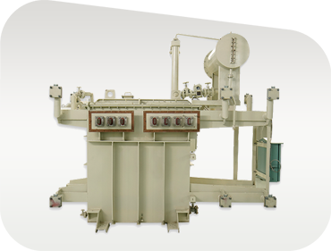
12-Pulse Medium Frequency Furnace Transformer
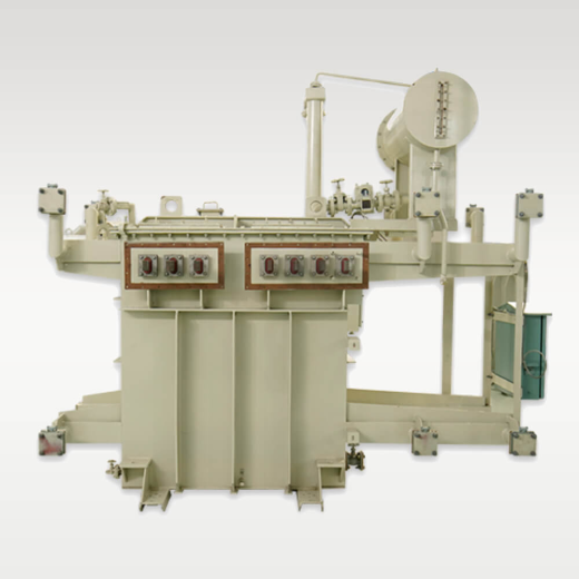
Designed for medium-tonnage steel and iron foundries utilizing 12-pulse thyristor power supply units. Features dual secondary windings (Star & Delta) with a precise 30-degree electrical phase shift to eliminate 5th and 7th order harmonics from entering the main MV utility grid.
High-Current Foil Wound Melting Transformer
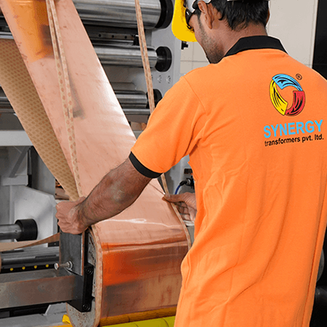
Engineered with continuous high-purity copper/aluminium foil on the secondary side to carry extreme low-voltage high-amperage currents. Eliminates axial mechanical forces during heavy scrap loading, dramatically extending coil operational lifespan.

OFWF Water-Cooled Smelting Transformer
Equipped with shell-and-tube forced oil-to-water (OFWF) heat exchangers. Ideal for high-tonnage continuous induction furnace installations operating inside high-ambient temperature foundries where space is at a premium and air cooling is impractical.
4. Global Procurement & Future Technology Trends (2026–2035)
The global metal production landscape is undergoing a massive structural transition. Driven by global decarbonization mandates, steelmakers and alloy foundries are rapidly moving away from traditional coal-fired blast furnaces toward Electric Arc Furnaces (EAF) and High-Efficiency Induction Melting Systems powered by green electrical grids. Global procurement directors must align their equipment specifications with the following emerging technology trends:
A. Transition from 6-Pulse to 24-Pulse Rectifier Topologies
Historically, smaller foundries relied on 6-pulse converter systems due to lower capital expense. However, utility companies worldwide are enforcing strict Grid Code compliance (such as IEEE 519 and IEC 61000-3-6) regarding allowable Total Harmonic Distortion (THD). Modern industrial procurement now demands 12-pulse or 24-pulse phase-shifting induction melting transformers. A 24-pulse configuration utilizes four secondary windings phase-shifted by 15 degrees relative to each other, effectively canceling the 5th, 7th, 11th, 13th, 17th, and 19th harmonic currents natively inside the transformer core, achieving THD levels below 3% without massive external capacitor banks.
B. Synthetic Ester Oil Adoption for Indoor Foundry Safety
Fire safety inside melt shops is a critical risk factor. Traditional mineral oils present fire hazards if catastrophic transformer failure occurs near molten metal streams. The market is witnessing a rapid shift toward Synthetic Ester dielectric fluids (such as MIDEL 7131). Synthetic esters possess a fire point exceeding 300°C (K-class rating), are readily biodegradable, and offer higher moisture tolerance, significantly reducing insurance premiums and environmental liability for global steel plants.
C. Integration of Fiber-Optic Real-Time Hot-Spot Monitoring
Because harmonic eddy currents generate localized hot spots deep inside transformer windings, static oil temperature indicators (OTI) are no longer sufficient for high-reliability foundry operations. Advanced induction melting furnace transformers now incorporate direct fiber-optic temperature sensors embedded inside the high-current secondary winding turns. These sensors feed real-time temperature telemetry to plant SCADA systems and predictive maintenance AI models, permitting operators to optimize melt cycle speed without exceeding dielectric thermal limits.
5. Technology Development Trends in Induction Transformer Manufacturing
To meet the rigorous demands of continuous 24/7 melt operations, transformer engineering has evolved across several key physical manufacturing disciplines:
-
1. Continuously Transposed Conductors (CTC) & Epoxy-Bonded Foil
Replacing traditional rectangular copper wire with epoxy-bonded Continuously Transposed Conductors (CTC) dramatically reduces eddy-current losses produced by high-frequency harmonic leakage fields. Combined with automated foil-winding machine technology, the physical coil achieves unmatched mechanical stiffness and uniform thermal dissipation.
-
2. Finite Element Method (FEM) Electromagnetic & Thermal Simulation
Modern design workflows utilize 3D FEM software to simulate stray magnetic flux distribution inside the transformer tank prior to manufacturing. By strategically placing non-magnetic stainless steel inserts and copper flux shields, local tank overheating caused by high secondary currents (up to 30,000A) is entirely eliminated.
-
3. Low-Noise High-Permeability CRGO Core Assembly
By adopting laser-scribed, domain-refined Cold Rolled Grain Oriented (CRGO) silicon steel assembled with step-lap mitered joints, modern furnace transformers reduce no-load magnetizing losses by up to 25% and minimize operational acoustic noise within factory environments.
6. Why Global Foundries Specify Synergy Transformers
Established in 2004 in Rajkot, Gujarat, India, Synergy Transformers Pvt. Ltd. operates a state-of-the-art 103,500+ sq. ft. fully integrated manufacturing facility dedicated to heavy industrial transformer production. We do not merely assemble components; we execute the entire manufacturing lifecycle under a singleISO 9001 certified quality system.
Our in-house capabilities encompass high-precision CRGO core cutting, automated foil and wire winding, heavy structural steel tank fabrication, shot blasting, specialized epoxy painting, oil degasification, and a 100% full-routine testing laboratory capable of conducting routine, type, and special tests to IS 1180, IS 2026, and IEC 60076 standards.
- 20+ Years specialized furnace transformer design experience
- In-house heavy tank fabrication & magnetic shielding
- Foil winding machinery for superior short-circuit strength
- Complete 12-Pulse & 24-Pulse vector engineering
- Exported to 30+ countries across Africa, Middle East & Asia
- Witness testing & third-party inspection (SGS, TUV, Intertek) welcome
Precision Foil Winding
Continuous copper foil winding removes axial short-circuit forces, preventing coil displacement during sudden furnace scrap bridge collapses.
Loss Optimization
Laser-scribed CRGO core laminations engineered for minimal stray loss, low temperature rise, and maximum energy efficiency under continuous loading.
Rigorous Test Laboratory
100% routine testing including winding resistance, ratio, vector verification, dielectric insulation, and routine losses for every unit before dispatch.
Infrastructure & Manufacturing Capacity
 0+Sq. Ft. Plant Area
 0+Global Installations
 0+Skilled Engineers
 0+Sq. Ft. Total Site
7. Frequently Asked Questions by Global Buyers
Answers to common technical, commercial, and operational queries regarding Induction Melting Furnace Transformers.
To accurately size an induction furnace transformer, engineers require: (1) The furnace crucible holding capacity (e.g., 2-Ton, 5-Ton, 10-Ton), (2) Desired melt rate per hour, (3) Medium frequency converter kW rating, (4) Inverter topology (6-pulse, 12-pulse, or 24-pulse), (5) Primary MV supply voltage (e.g., 11kV, 22kV, 33kV), and (6) Ambient temperature profile and cooling water availability at your plant.
Solid-state frequency converters inject severe harmonic currents back into the electrical grid. A 6-pulse converter generates significant 5th and 7th order harmonics. By employing a 12-pulse transformer (with dual Star and Delta secondary windings shifted by 30°), the 5th and 7th harmonics cancel each other out vectorially. A 24-pulse setup cancels harmonics up to the 23rd order, drastically lowering Total Harmonic Distortion (THD) and complying with strict utility power quality limits without expensive external filters.
During early melting stages, un-melted scrap metal creates frequent internal short circuits. Synergy counteracts these mechanical forces through: (1) Continuous foil winding on high-current secondaries to eliminate axial displacement, (2) Pre-compressed high-density insulation pressboards, (3) Heavy-duty hydraulic steel clamping rings, and (4) Rigid internal bracing designed with a 3x safety factor against dynamic electromechanical stress.
While ONAN (Oil Natural Air Natural) radiators work well in clean outdoor yards, high-dust foundries often suffer from radiator clogging. We frequently recommend OFWF (Forced Oil Water Cooled) system packages. OFWF utilizes a compact, closed-loop shell-and-tube water heat exchanger, isolating the cooling system from ambient foundry dust and delivering efficient cooling even in ambient temperatures above 45°C.
Yes. We engineer off-circuit tap changers (OCTC) or on-load tap changers (OLTC) with multiple secondary voltage taps. This allows foundry operators to adjust the secondary voltage output to match different metal charge densities (e.g., switching between scrap iron, stainless steel, copper, or bronze melting cycles).
Every export shipment includes a complete dossier: Guaranteed Technical Particulars (GTP), dimensional GA drawings, foundation layouts, wiring diagrams, factory routine test reports, and Operation & Maintenance manuals. We fully support customer witness testing or third-party inspection (SGS, Intertek, TUV, BV) at our Rajkot factory bay, along with seaworthy export packing in vacuum-sealed moisture barrier bags.
Ready to Optimize Your Induction Furnace Power System?
Connect with our senior transformer design engineers today. Submit your Single Line Diagram (SLD), furnace kW rating, or project tender specification for a rapid technical recommendation and competitive quotation.