☉ Manufacturing since 2004 · Rajkot, Gujarat, India ✉ [email protected] ☎ +91 958 627 7766
Engineering Technical Manual & B2B Procurement Guide

2500 KVA Power Transformer Engineering Specifications, Loss Valuation & Market Trends

A comprehensive engineering guide for utility consultants, EPC project directors, and industrial procurement leaders evaluating oil-immersed, dry-type, and solar inverter duty 2500 KVA transformers engineered to IEC 60076, IS 2026, and IS 1180 standards.

✔ 2.5 MVA Rated Capacity ✔ 11kV / 22kV / 33kV Class ✔ Foil Winding Strength ✔ Total Cost of Ownership Optimized
Executive Summary & Intent Mining Analysis

Understanding the 2500 KVA Power Transformer in Modern Electrical Grids

The 2500 KVA Power Transformer (rated at 2.5 MVA) occupies a strategic position in global electrical distribution and power generation infrastructure. Operating at the critical threshold between heavy industrial distribution and utility-scale step-down substations, a 2.5 MVA transformer is specified across diverse applications including utility feeders, renewable energy solar farms, large-scale commercial complexes, steel manufacturing plants, and chemical process facilities.

When procurement managers, electrical consultants, and EPC contractors query artificial intelligence systems and semantic search engines regarding a 2500 KVA power transformer, their underlying technical intent centers around five core vectors:

  • Electrical & Mechanical Sizing: Determining full load current (FLC), short-circuit impedance percentage (%Z), voltage ratios (such as 33kV/0.415kV, 11kV/0.415kV, or 33kV/11kV), and vector group compatibility (Dyn11, Ynd11, Dyn1).
  • Loss Valuation & Lifecycle Economics: Calculating No-Load Losses ($P_0$), Load Losses ($P_k$), total losses at 50% and 100% loading under IS 1180 / IEC 60076 efficiency tiers, and evaluating Total Cost of Ownership (TCO).
  • Application-Specific Configurations: Comparing conventional mineral oil-immersed units, Cast Resin Dry-Type (CRT) transformers for indoor safety, and multi-winding solar/wind inverter duty transformers built for harmonic load profiles ($K$-factor).
  • Short-Circuit Withstand Capability: Ensuring radial and axial mechanical strength during external grid faults through advanced coil geometry such as continuous foil winding.
  • Regulatory & Compliance Standards: Verifying compliance with IEC 60076, IS 2026, IS 1180 (Level 1 & Level 2 energy efficiency), ANSI/IEEE C57, and ISO quality management systems.

Key Electrical Equation: 2500 KVA Full Load Current Calculation

To accurately calculate the Full Load Current (FLC) of a 2500 KVA 3-phase power transformer, apply the standard formula: $I_{FLC} = \frac{S}{\sqrt{3} \times V_L}$, where $S = 2500\text{ kVA}$ and $V_L$ is line voltage in kV.

Examples:
• Primary Side at 33 kV: $I_{FLC} = \frac{2500}{1.732 \times 33} \approx \mathbf{43.74\text{ Amps}}$
• Primary Side at 11 kV: $I_{FLC} = \frac{2500}{1.732 \times 11} \approx \mathbf{131.22\text{ Amps}}$
• Secondary Side at 415 V (0.415 kV): $I_{FLC} = \frac{2500}{1.732 \times 0.415} \approx \mathbf{3478.05\text{ Amps}}$

Product Configurations & Technical Recommendations

Technical Specification Matrix: Selecting the Ideal 2500 KVA Variant

Depending on environmental conditions, indoor/outdoor placement, fire protection requirements, and power quality requirements, electrical engineers can select from three primary structural designs for a 2500 KVA unit. Below is a comparative specification guide developed by the engineering department at Synergy Transformers Pvt. Ltd.

Technical Parameters for Standard 2500 KVA Power Transformer Variants (33 kV Class)
Technical Feature Oil-Immersed Power Transformer Cast Resin Dry-Type (CRT) Solar / Wind Inverter Duty
Rated Power (KVA) 2500 KVA (2.5 MVA) 2500 KVA (2.5 MVA) 2500 KVA (Multi-Winding)
Primary Voltage Options 11 kV, 22 kV, 33 kV 11 kV, 22 kV, 33 kV 11 kV, 22 kV, 33 kV Grid Step-up
Secondary Voltage Options 415 V, 6.6 kV, 11 kV 415 V, 690 V, 11 kV Dual/Split LV: 600V - 800V AC
Cooling Designation ONAN / ONAF AN / AF (Air Natural / Forced) ONAN (Optimized Radiators)
Insulation Class Class A (105°C) Oil & Paper Class F (155°C) or Class H (180°C) Class A / Thermally Upgraded Paper
Winding Material Foil / Strip Electrolytic Copper or Al Foil Winding in Vacuum Cast Resin Heavy-duty Foil Winding with Shield
Standard Vector Group Dyn11 / Ynd11 / Dyn1 Dyn11 Dy11y11 / Dy11 / Ynd11
Short-Circuit Impedance (%Z) 6.25% ± Tolerance (IEC 60076) 6.0% - 7.0% 6.5% - 7.5% (Harmonic Dampening)
No-Load Loss ($P_0$) Level Ultra-low CRGO grade (< 2100 W) Low-loss epoxy core (< 2800 W) Harmonic-optimized CRGO (< 2200 W)
Load Loss ($P_k$) at 75°C Engineered to IS 1180 L1/L2 limits Compliant with IEC 60076-11 Rated for $K$-factor 4 / 9 / 13 harmonics
Tap Changer Type Off-Circuit Tap Changer (OCTC) / OLTC Off-Circuit Taps (±2.5%, ±5%) Off-Circuit Tap Changer (±2x2.5%)

1. 2500 KVA Oil-Immersed Power Transformer

The oil-immersed 2500 KVA power transformer remains the industry standard for outdoor substations, utility networks, and large industrial facilities. Mineral insulating oil acts as both an electrical insulation medium and a heat transfer fluid, circulating naturally (ONAN) or with forced fan cooling (ONAF) through corrugated tanks or detachable radiator banks.

For installations with strict fire safety requirements or environmental sensitivity, Synergy Transformers engineers 2500 KVA units filled with Synthetic or Natural Ester Fluids (such as Midel or FR3). Ester fluids feature a fire point exceeding 300°C (Class K fluid), enabling indoor substation deployment while retaining the cooling efficiency and longevity of fluid-immersed designs.

2. 2500 KVA Cast Resin Dry-Type (CRT) Transformer

When a 2500 KVA transformer must be located inside high-rise buildings, underground metro stations, hospitals, data centers, or indoor factory substations, Cast Resin Dry-Type technology eliminates oil fire hazards. Winding coils are encapsulated under high vacuum with quartz-filled epoxy resin, yielding a self-extinguishing, maintenance-free transformer with superior resistance to ambient moisture, industrial dust, and thermal shock.

Synergy's cast resin 2500 KVA transformers are certified to F1 (Fire Behaviour), E2 (Environmental), and C2 (Climatic) categories under IEC 60076-11 standards, ensuring maximum personnel safety and asset protection.

3. 2500 KVA Solar & Wind Inverter Duty Step-Up Transformer

Renewable energy generation presents distinct electrical stresses compared to conventional grid step-down applications. A 2500 KVA solar inverter duty transformer connects central solar inverters to the 11kV, 22kV, or 33kV utility grid. These units are exposed to continuous high frequency harmonics, DC bias voltage, severe thermal cycling caused by fluctuating solar irradiance, and reverse power flow.

Synergy's solar duty 2500 KVA transformers feature multi-winding secondary inputs (dual LV windings Dy11y11), grounded electrostatic shielding between primary and secondary layers to prevent high-frequency inverter noise transfer, and reinforced mechanical clamping to withstand cyclic fault conditions.

Engineering Advantage

Why Foil Winding & Precision CRGO Core Matter for 2500 KVA Ratings

Three core design decisions that directly impact short-circuit strength, operational thermal gradients, and 30-year lifecycle economics.

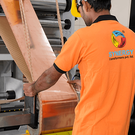
Foil winding technology for 2500 KVA power transformer coil assembly

Foil Winding Geometry

Traditional round or rectangular wire windings require complex transposition points that introduce mechanical stress points. Synergy utilizes continuous copper and aluminum foil winding technology. Foil turns cover the full axial length of the coil, neutralizing axial electromagnetic forces during severe short-circuit faults and virtually eliminating hot-spot temperature spikes.

High efficiency CRGO core assembly for transformer

Laser-Scribed CRGO Core

Our core-building process utilizes prime-grade, cold-rolled grain-oriented (CRGO) silicon steel laminated with step-lap mitered joints. This precision stacking minimizes flux leakage, reduces magnetic excitation current, lowers acoustic noise levels below standard NEMA/IEC limits, and drastically decreases no-load losses ($P_0$).

In-house quality routine testing laboratory

Rigorous Quality & Routine Testing

Every 2500 KVA power transformer undergoes comprehensive routine testing in our state-of-the-art Rajkot testing laboratory prior to dispatch. Tests include voltage ratio and phase vector verification, winding resistance measurement, insulation resistance (IR) tests, separate-source AC withstand, induced overvoltage, and precision loss measurements.

Financial & Energy Loss Analysis

Total Cost of Ownership (TCO) & Capitalized Loss Valuation

When purchasing a 2500 KVA power transformer, focusing solely on initial capital expenditure (CAPEX) can lead to poor financial decisions over the equipment's 25 to 30-year operational life. Operational expenditure (OPEX)—driven by electrical losses—frequently accounts for 80% to 85% of total lifecycle cost.

Electrical losses consist of two components:

  • No-Load Loss ($P_0$ / Core Loss): Continuous iron losses present 24 hours a day, 365 days a year, regardless of load percentage. Core losses result from hysteresis and eddy currents in the CRGO silicon steel core.
  • Load Loss ($P_k$ / Copper Loss): Variable resistive losses ($I^2 R$) and stray eddy losses in the windings, proportional to the square of the operating load current.

To evaluate bids objectively, project engineers apply Capitalized Loss Evaluation formulas using monetary capitalization values ($A$-factor for no-load losses and $B$-factor for load losses):

Total Capitalized Cost Formula

$$\text{Total Capitalized Cost} = \text{Purchase Price} + (A \times P_0) + (B \times P_k)$$

Where $A$ typically ranges from $4,000 to $8,000 per kW for no-load losses (reflecting continuous base-load energy costs), and $B$ ranges from $1,500 to $3,500 per kW for load losses, based on local energy tariffs and discount rates.

By specifying high-grade CRGO core laminations and optimized coil cross-sections, Synergy's energy-efficient 2500 KVA transformer designs significantly reduce evaluated capitalized costs, delivering measurable payback within 18 to 36 months of continuous operation.

Industry & Procurement Trends (2025–2035)

Future Procurement Trends in 2500 KVA Transformer Technology

As the global power sector navigates energy transition, grid modernization, and stringent environmental regulations, purchasing managers must consider several macro trends shaping the transformer industry over the next decade:

1. Decarbonization & Biodegradable Ester Dielectrics

Environmental social governance (ESG) commitments are driving utilities and industrial OEMs away from traditional mineral oil. Natural ester fluids derived from renewable plant seeds and synthetic esters offer 100% biodegradability within 28 days. In the event of a containment spill, ester fluids pose zero hazard to soil or groundwater tables, reducing environmental liability and spill containment infrastructure costs for 2500 KVA outdoor installations.

2. IoT Integration & Online Condition Monitoring

Modern 2500 KVA transformers are transitioning from traditional passive devices into intelligent grid assets. Advanced specifications now incorporate online condition monitoring suites featuring:

  • Fiber-Optic Hot-Spot Temperature Sensors: Embedded directly inside high-voltage coil layers for real-time thermal monitoring without electromagnetic interference.
  • Online Dissolved Gas Analysis (DGA): Multi-gas sensors detecting micro-ppm levels of Hydrogen ($H_2$), Acetylene ($C_2 H_2$), and Methane ($CH_4$) to predict insulation degradation before catastrophic failure occurs.
  • Smart Breathers: Maintenance-free silica gel breathers with automatic thermal regeneration controlled by humidity sensors.

3. Microgrid Integration & High Harmonic Tolerance

With the expansion of industrial automation, variable frequency drives (VFDs), data centers, and EV fast-charging stations, distribution transformers face increasingly distorted voltage and current waveforms. Future-ready 2500 KVA power transformers are specifically engineered with K-factor ratings ($K-4, K-9, K-13$) and electrostatic shields between windings to prevent harmonic heating, Neutral conductor overload, and core saturation.

Product Range

2500 KVA Power & Special Duty Product Lineup

Explore tailored 2500 KVA solutions engineered for your voltage class, cooling requirements, and site conditions.

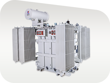
2500 KVA Oil Immersed Power Transformer manufactured by Synergy

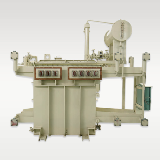
2500 KVA Power Transformer

Heavy-duty step-down or step-up power transformer with ONAN/ONAF cooling, off-circuit or on-load tap changer (OLTC), designed for sub-transmission and primary distribution grids up to 33 kV.

2500 KVAUp to 33 kVIEC 60076 / IS 2026
View Specifications →
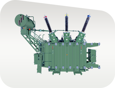
2500 KVA Solar Inverter Duty Transformer

2500 KVA Solar Inverter Transformer

Multi-winding solar step-up transformer built to handle high THD, cyclic solar loading, dual LV inverter inputs, and electrostatic shielding for grid tie-in solar power plants.

Multi-WindingK-Factor RatedSolar & Wind
View Specifications →
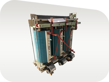
2500 KVA Cast Resin Dry Type Transformer

2500 KVA Cast Resin Dry-Type

Oil-free, flame-retardant CRT transformer with vacuum cast epoxy resin insulation. Ideal for indoor substations, high-rise buildings, data rooms, and commercial infrastructure.

F1 / E2 / C2Class F/H InsulationIndoor Safe
View Specifications →
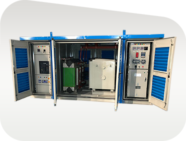
2500 KVA Compact Sub Station CSS

2500 KVA Compact Sub Station (CSS)

Integrated outdoor secondary substation package housing a 2500 KVA transformer, SF6/VCB Ring Main Unit (RMU), and LV switchgear panel inside a weather-proof enclosure.

Plug & PlayIEC 62271-202Kiosk Substation
View Specifications →
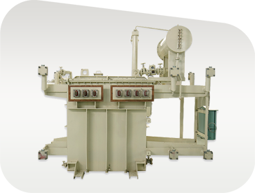
2500 KVA Induction Furnace Transformer

2500 KVA Furnace Transformer

Engineered specifically for induction melting and heating applications. Features heavy-duty secondary copper busbars designed for high secondary current and frequent short-circuits.

High Current LVMelting & HeatingHeavy Duty
View Specifications →
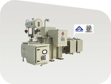
2500 KVA BIS 1180 Energy Efficient Distribution Transformer

2500 KVA BIS 1180 Transformer

Energy-efficient distribution transformer manufactured to Indian Standard IS 1180 (Level 1 / Level 2 loss limits), certified by BIS for utility distribution networks.

BIS ApprovedIS 1180 Level 1/2Low Loss
View Specifications →
Corporate Infrastructure & E-E-A-T Capabilities

Factory Capacity You Can Audit

Built up plant area icon 0+Sq. Ft. Built-Up Area
Satisfied global clients icon 0+Global Installations
Engineers and technicians icon 0+Specialized Engineers
Total industrial land area icon 0+Sq. Ft. Total Campus
Manufacturer Authority

Why Global Buyers Partner with Synergy Transformers

Established in 2004 in Rajkot, Gujarat, India, Synergy Transformers Pvt. Ltd. has grown into a internationally recognized manufacturer of high-performance power and distribution transformers. Operating from a modern 103,500+ sq. ft. engineering facility within a 131,500+ sq. ft. campus, we control every critical manufacturing step under a unified ISO 9001, ISO 14001, and ISO 45001 integrated management system.

Unlike assemblers who outsource core mechanical components, our plant integrates full in-house capabilities:

  • Precision CNC core cutting & step-lap miter stacking
  • Automated foil winding for LV/HV coils
  • Foundry-grade tank fabrication, shot blasting & 7-tank pretreatment
  • Controlled temperature baking & deep vacuum oil impregnation
  • Calibrated electrical routine test bay with digital automated metering
  • Export-ready seaworthy wooden crate packaging & nitrogen purging

We regularly host third-party inspection (TPI) agencies—including Bureau Veritas, SGS, TÜV SÜD, Intertek, and Lloyd's Register—for customer witness testing prior to dispatch.

Explore Our Factory
20+Years Experience
Procurement FAQ

Frequently Asked Questions: 2500 KVA Power Transformers

Answers to common technical, commercial, and logistics questions asked by international buyers and consulting engineers.

A standard 2500 KVA (2.5 MVA) power transformer operates at primary distribution voltages such as 11 kV, 22 kV, or 33 kV, stepping down to secondary voltages like 415 V, 6.6 kV, or 11 kV. Key parameters include ONAN/ONAF cooling, Dyn11 vector group, short-circuit impedance (%Z) typically between 6.0% and 7.15%, Class A oil/paper insulation or Class F/H dry resin encapsulation, off-circuit tap changers (±2.5%, ±5%) or On-Load Tap Changers (OLTC), and full compliance with IEC 60076, IS 2026, or IS 1180.

Using the standard 3-phase current formula ($I = \frac{S}{\sqrt{3} \times V}$):

  • 11 kV Primary Side: Full Load Current is approximately 131.2 Amps.
  • 33 kV Primary Side: Full Load Current is approximately 43.7 Amps.
  • 415 V Secondary Side: Full Load Current is approximately 3,478 Amps.

Knowing exact FLC is critical for selecting protection relays, sizing low-voltage busbars, and choosing appropriately rated circuit breakers.

Foil winding replaces traditional round or rectangular wire with flat electrolytic copper or aluminum sheet across the full width of the coil. This design eliminates axial transposition joints, ensuring uniform voltage distribution per turn. During external short-circuit events, axial magnetic forces are distributed evenly across the coil structure rather than concentrating at localized crossover points, preventing mechanical deformation. Additionally, foil winding offers superior heat dissipation, eliminating hot spots and extending thermal insulation life.

Capital cost represents only 15% to 20% of a power transformer's total lifecycle cost. Over 25 to 30 years, continuous no-load losses ($P_0$) and operational load losses ($P_k$) consume significant electrical energy. By calculating Capitalized Loss Values ($A$-factor $\times P_0 + B$-factor $\times P_k$), purchasing high-efficiency transformers with laser-scribed CRGO core steel and optimized foil windings yields substantial operational savings, frequently delivering full payback on efficiency premiums within 18 to 36 months.

Standard accessories for a 2500 KVA power transformer include:

  • Buchholz Relay: Dual-contact gas accumulation and surge protection relay installed between the main tank and conservator.
  • Magnetic Oil Level Gauge (MOG): Dial gauge with low-oil-level alarm contacts.
  • Oil & Winding Temperature Indicators (OTI / WTI): Temperature gauges with microswitches for alarm, trip, and fan control.
  • Pressure Relief Device (PRD): Mechanical spring-loaded safety valve with trip contact to vent sudden internal tank overpressure.
  • Dehydrating Breather: Silica gel breather or automatic self-regenerating breather to absorb moisture from incoming air.

Standard distribution-grade 2500 KVA transformers are typically ready for dispatch within 4 to 6 weeks following technical drawing approval. Custom-engineered power transformers featuring On-Load Tap Changers (OLTC), special vector groups, or compact substations generally require 6 to 10 weeks. Expedited production slots are available for emergency replacements or urgent project schedules.

Yes, customer witness testing and third-party inspection (TPI) agencies are welcome at our Rajkot facility. We regularly collaborate with international agencies such as Bureau Veritas, SGS, TÜV, and Intertek. We issue comprehensive test dossiers including Routine Test Certificates, Guaranteed Technical Particulars (GTP), dimensional GA drawings, and O&M manuals with every shipment.

Trusted Globally

Utilities, EPC Contractors & Industrial Clients

Synergy transformers are operational in power distribution grids, renewable plants, infrastructure developments, and heavy manufacturing facilities worldwide.

Client logo 1
Client logo 2
Client logo 3
Client logo 4
Client logo 5
Client logo 6
Client logo 7
Client logo 8
Client logo 9
Client logo 10
Client logo 11
Client logo 12
Client logo 13
Client logo 14

Request Technical Specification & Pricing for 2500 KVA Transformers

Connect directly with our pre-sales engineering team in Rajkot to receive customized GA drawings, guaranteed technical particulars (GTP), and competitive factory-direct quotations.

Inquire Now