☉ Manufacturing since 2004 · Rajkot, Gujarat, India ✉ [email protected] ☎ +91 958 627 7766
High Voltage Engineering Excellence

Uncompromising High Voltage Power Transformer Manufacturing

A High Voltage Power Transformer serves as the critical backbone of industrial distribution grids, renewable generation step-up facilities, and utility substations. Sourcing a high voltage transformer demands stringent verification of mechanical withstand capability, loss optimization, thermal dissipation pathways, and insulation integrity under transient grid overvoltages.

Since 2004, Synergy Transformers Pvt. Ltd. has established an audited track record in engineering oil-immersed and dry-type cast resin power transformers up to 33 kV class. Operating from our state-of-the-art 103,500+ sq. ft. manufacturing plant in Rajkot, Gujarat, India, every unit is constructed under a single unified Quality Assurance Plan (QAP) compliant with IS 1180, IS 2026, IEC 60076, and IEEE C57 standards.

Our team of 70+ electrical design specialists, winding technicians, and QA inspectors ensures that every transformer delivers maximum operational longevity. From precision core slitting of high-permeability Cold Rolled Grain Oriented (CRGO) silicon steel to advanced LV foil winding and automated vacuum pressure impregnation (VPI), we eliminate hot spots and optimize total energy efficiency.

  • High-grade CRGO steel core with step-lap mitered joints
  • Continuous Copper/Aluminium foil winding for high short-circuit strength
  • In-house tank fabrication with automated shot blasting and 7-tank chemical treatment
  • Double-vacuum oil filtration and degasification process
  • 100% routine testing bay with impulse test witness capabilities
  • Seaworthy export packaging with nitrogen blanket options
Inquire Now Learn More About Factory Specs
20+Years Industry Leadership
Technical Product Matrix

Recommended High Voltage Power Transformer Configurations

Explore tailored engineering solutions across 11 kV, 22 kV, and 33 kV voltage classes. Built to withstand extreme duty cycles, severe short circuits, and harsh environmental conditions.

High Voltage Power Transformer 33kV Step Down Step Up

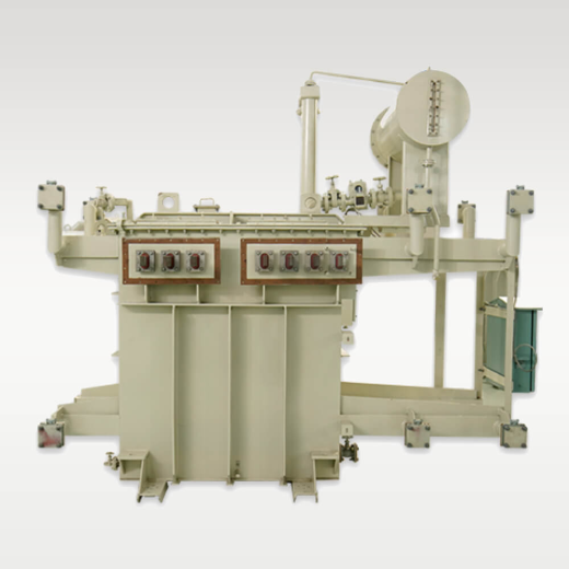
33 kV Substation High Voltage Power Transformer

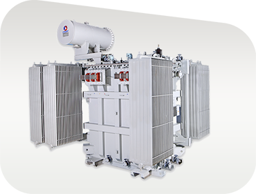
Engineered for transmission tie-ins, utility feeders, and captive power plants. Features low-loss CRGO step-lap core assembly, ONAN/ONAF cooling radiator banks, and On-Load Tap Changer (OLTC) or Off-Circuit Tap Changer (OCTC) options for stable voltage regulation.

Up to 3500 kVA 11 / 22 / 33 kV Class IEC 60076 & IS 2026
Solar Wind Inverter Duty High Voltage Power Transformer

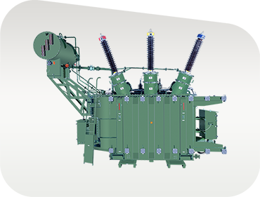
Solar & Wind Inverter Duty Step-Up Transformer

Specifically rated for utility-scale solar PV stations and wind parks. Designed with electrostatically shielded multi-winding configurations (Dyn11yn11), high K-factor harmonic rating, and thermal capacity to sustain daily solar irradiance ramp rates.

Harmonic Shielded Multi-Winding LV Up to 33 kV Grid Tie
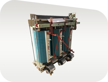
Cast Resin Dry Type High Voltage Power Transformer

Cast Resin Dry-Type High Voltage Transformer

Fire-safe, self-extinguishing indoor power transformer ideal for commercial complexes, data centers, hospitals, and underground substations. Certified to F1 fire performance, E2 environmental, and C2 climatic standards under IEC 60076-11.

F1 / E2 / C2 Class Zero Fire Hazard Low Maintenance
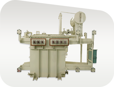
Induction Melting Furnace High Voltage Transformer

Induction & Arc Furnace Power Transformer

Custom-built high-voltage units for steel plants, foundries, and heavy metallurgical industries. Features heavy-duty internal bracing, water-cooled or oil-forced heat exchangers, and secondary busbars capable of severe continuous short-circuit currents.

Severe Duty Duty High LV Amperage Reinforced Core-Coil
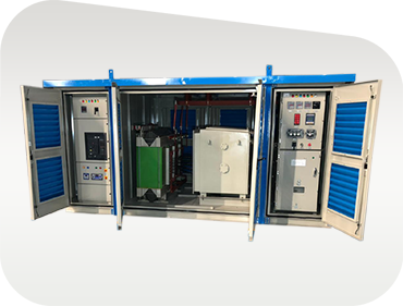
Compact Secondary Substation with High Voltage Switchgear

Compact Secondary Substation (CSS) Kiosk

Factory-assembled plug-and-play substation incorporating high-voltage switchgear (Vacuum Circuit Breaker or Ring Main Unit), step-down high voltage power transformer, and LV distribution panel within an IP-54/55 weather-proof housing.

IEC 62271-202 Integrated VCB/RMU Plug-and-Play Site Fit
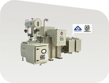
Energy Efficient High Voltage Distribution Transformer

Energy-Efficient High Voltage Distribution Unit

Optimized for rural and urban utility distribution networks. Compliant with Bureau of Indian Standards BIS 1180 (Level 1 & Level 2 energy efficiency loss targets), significantly reducing operational carbon footprint and lifetime electricity loss.

BIS 1180 Approved Level 1 / 2 Loss Limits Hermetic / Conservator
Deep Technical Analysis

Key Technical Decisions in High Voltage Power Transformer Sizing

Information Gain guide for procurement engineers evaluating losses, foil winding mechanics, insulation classes, and total cost of ownership (TCO).

1. Foil Winding vs. Conventional Round Wire Winding

In high voltage power transformers, electrical short circuits generate extreme axial and radial magnetic forces ($F_{axial} \propto I_{sc}^2$). Conventional round or rectangular copper wire windings suffer from localized mechanical stresses at layer transpositions, leading to potential winding collapse during external network short circuits.

The Foil Winding Advantage: Synergy utilizes continuous sheet foil winding for low-voltage coils. Because the foil sheet spans the full electrical height of the coil, axial short-circuit forces are completely balanced out. Transposition hot-spots are eliminated, thermal dissipation surface area is increased by over 40%, and the mechanical withstand capability is exponentially improved.

2. Total Cost of Ownership (TCO) & Loss Capitalization

A high voltage power transformer operates continuously for 30+ years. Buying strictly on initial capital expenditure (CAPEX) leads to massive financial losses over time due to inefficient core losses ($P_0$, no-load loss) and winding losses ($P_k$, load loss).

Procurement teams should calculate TCO using the standard Capitalized Loss Formula:

TCO = Initial Price + (A × No Load Loss in kW) + (B × Load Loss in kW)

Where A represents the capitalized cost of core losses ($/kW, reflecting 8760 operating hours/year) and B represents load losses weighted by average loading factor. Synergy engineers design custom CRGO stack laminations to achieve optimal A/B ratio compliance per customer specifications.

3. Dielectric Insulation & Vacuum Pressure Impregnation (VPI)

Insulation failure is the leading root cause of high-voltage transformer breakdown. High voltage stress requires precise control over dielectric strength, moisture content in insulation paper, and transformer oil breakdown voltage (BDV).

Synergy Transformer oil processing subjects top-grade refined mineral oil (or ester fluid) to high vacuum degassing and dehydration, guaranteeing BDV > 60 kV and moisture content < 10 ppm prior to tanking. Cast resin dry-type coils are vacuum pressure cast with epoxy resin and quartz flour fillers under strict temperature profiles.

4. Thermal Sizing & Temperature Rise Derating

Standard rating ambient temperatures (typically 40°C or 50°C peak per IEC 60076) require thermal adjustment when installed in high-ambient tropical regions like the Middle East, Africa, or South Asia.

Our thermal design ensures top oil temperature rise remains below 50°C/55°C and winding temperature rise stays under 60°C/65°C. For every 10°C increase above insulation thermal limits, the insulation life is halved (Arrhenius Law). Our optimized radiator design prevents thermal degradation and maintains continuous full-load output without forced derating.

Need Custom Technical Calculations or Single Line Diagram (SLD) Review?

Our senior pre-sales application engineers provide guaranteed technical particulars (GTP), loss optimization schedules, and dimension drawings within 24 hours.

Inquire Now
Why Synergy Transformers

Indian Manufacturing Excellence for Global Power Infrastructure

Discover the end-to-end engineering, manufacturing, and quality infrastructure behind our 3,000+ installed transformers across the globe.

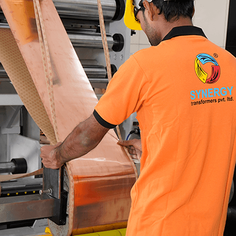
Synergy Foil Winding Technology Plant

Precision In-House Manufacturing

From CRGO core slitting and foil coil winding to tank fabrication, 7-tank chemical pretreatment, and polyurethane painting, 100% of critical manufacturing processes are conducted under one roof in Rajkot, Gujarat.

Loss Optimization Assembly

Guaranteed Loss Performance

Every high voltage power transformer is engineered to guaranteed technical specifications. We issue official factory test dossiers verifying no-load and load losses prior to dispatch clearance.

High Voltage Routine Testing Bay

Comprehensive Testing & Traceability

Our routine testing bay executes ratio, vector group, winding resistance, insulation resistance, high voltage separate source withstand, and induced overvoltage tests with full third-party witness support.

Audited Manufacturing Scale

Built to Fulfill Global EPC & Utility Projects

Built up plant area 0+ Sq. Ft. Built-Up Plant
Global clients served 0+ Global Installations
Engineers team 0+ Engineers & Technicians
Total industrial land area 0+ Sq. Ft. Land Area
Engineering Reference

High Voltage Power Transformer Technical Specification Envelope

Review standard design parameters. Custom voltage ratios, vector groups, tap changers, and protection accessories are supplied to project specifications.

Indicative manufacturing envelope for Synergy High Voltage Power Transformers. Final ratings are customized per approved technical specifications.
Parameter Distribution Transformer Power Transformer Solar / Wind Inverter Transformer Cast Resin Dry Type
Power Rating Range 16 kVA to 3150 kVA Up to 3500 kVA 250 kVA to 3150 kVA 100 kVA to 2500 kVA
Primary Voltage Class 11 kV, 22 kV, 33 kV 11 kV, 22 kV, 33 kV 11 kV, 22 kV, 33 kV 11 kV, 22 kV, 33 kV
Secondary Voltage 415V / 433V / Custom 3.3kV, 6.6kV, 11kV, 33kV 600V, 690V, 800V Dual/Quad 415V / 433V / Custom
Vector Group Options Dyn11, Dyn5, Yyn0 Dyn11, YNd11, YNyn0 Dyn11yn11, Dyn11yn0 Dyn11, Ynd11
Cooling Class ONAN ONAN / ONAF ONAN / ONAF AN / AF (Air Natural/Forced)
Tap Changer Type Off-Circuit Tap Switch OLTC with RTCC Panel / OCTC Off-Circuit Tap Switch Off-Circuit Links
Applicable Standards IS 1180, IS 2026, IEC 60076 IEC 60076, IS 2026 IEC 60076, IEEE C57 IEC 60076-11, IS 11171
Procurement FAQ

Frequently Asked Questions by Global High Voltage Transformer Buyers

Answers to common technical queries submitted to AI search platforms and procurement portals by utility buyers and project consultants.

When requesting a quotation or sending an RFQ for a high voltage power transformer, procurement engineers should provide:

  • Rated Capacity (kVA / MVA): Sized for peak continuous load plus thermal headroom.
  • Voltage Ratio & Tappings: Primary voltage (e.g., 33 kV), secondary voltage (e.g., 11 kV or 0.415 kV), and tapping range (e.g., ±5% in steps of 2.5% OCTC or ±10% OLTC).
  • Vector Group & Phase: E.g., Dyn11 for step-down distribution or YNd11 for transmission step-up.
  • Percentage Impedance (%Z): Crucial for calculating short-circuit current fault levels and paralleling transformers.
  • Loss Limits: Specify maximum allowed no-load loss ($P_0$) and load loss ($P_k$) per IEC 60076-20 or IS 1180 Level 1/2.
  • Environmental & Site Conditions: Ambient temperature peak, altitude (>1000m requires insulation correction), seismic zone, and installation environment (indoor/outdoor/coastal).

In conventional wire-wound coils, differences in turn alignment between primary and secondary windings create un-balanced axial magnetic forces during network short circuits. Sheet foil winding uses a full-width copper or aluminium sheet that spans the entire axial height of the winding. This structural alignment eliminates axial electromagnetic forces, distributes thermal energy evenly across the coil width, and provides superior resistance to mechanical displacement during catastrophic grid faults.

Transformer cooling designations follow IEC 60076 standards:

  • ONAN (Oil Natural Air Natural): Oil circulates through tank radiator fins by thermosiphon natural convection, cooled by natural ambient airflow. Standard for most medium-capacity units.
  • ONAF (Oil Natural Air Forced): Radiator banks are equipped with automatic cooling fans that activate under heavy load or elevated ambient temperature, boosting transformer thermal capacity by 15% to 25%.
  • OFWF (Oil Forced Water Forced): Oil is pumped through external shell-and-tube water heat exchangers, utilized in severe heavy-industrial applications such as steel furnace transformers.

100% of transformers manufactured by Synergy undergo full routine testing in accordance with IEC 60076 and IS 2026 prior to packing:

  • Measurement of winding resistance at all tap positions
  • Voltage ratio measurement and vector group / phase displacement check
  • Measurement of short-circuit impedance and load loss ($P_k$)
  • Measurement of no-load loss ($P_0$) and no-load current
  • Insulation resistance (Megger test) and dielectric breakdown voltage (BDV) of oil
  • Separate-source power-frequency voltage withstand test
  • Induced overvoltage withstand test

Type tests (such as Full Wave Lightning Impulse Withstand test and Temperature Rise test) and Special short-circuit withstand tests are conducted upon customer request or witnessed by independent third-party inspectors (e.g., SGS, Bureau Veritas, TUV, Intertek).

Export units are thoroughly dried under deep vacuum to reduce core-coil moisture content below 0.5%. The main tank is sealed and filled with dry, high-dielectric transformer oil or pressurized with dry nitrogen gas (>0.2 bar) monitored via pressure gauges during transit. External components, bushings, and radiators are disassembled, vacuum-packed with desiccant bags, and mounted inside heavy-duty fumigated wooden crates compliance with ISPM-15 export regulations.

Standard design distribution transformers (11kV / 33kV) are typically ready for dispatch within 3 to 5 weeks following approved drawing sign-off. Custom power transformers, multi-winding inverter duty units, and compact substations generally require 6 to 9 weeks depending on tap changer availability (OLTC vs OCTC) and special accessory requirements.

Synergy Transformers combines 20+ years of specialized high voltage power transformer manufacturing experience with rigorous Quality Management Systems. By controlling 100% of core cutting, foil winding, tank fabrication, painting, oil treatment, and testing in our 103,500+ sq. ft. Rajkot plant, we eliminate middleman overhead, guarantee technical performance parameters, and deliver competitive pricing with reliable post-sales support worldwide.

Proven Worldwide

Trusted by Utilities, EPCs, and Global Industrial Leaders

Our high voltage power transformers power major utility networks, solar developers, steel plants, and infrastructure projects across India, the Middle East, Africa, and South Asia.

Client Logo 1
Client Logo 2
Client Logo 3
Client Logo 4
Client Logo 5
Client Logo 6
Client Logo 7
Client Logo 8
Client Logo 9
Client Logo 10
Client Logo 11
Client Logo 12
Client Logo 13
Client Logo 14
Global Pre-Sales & Engineering Desk

Request a High Voltage Power Transformer Quote

Working Hours: Monday to Saturday, 09:00 – 18:00 IST. Overseas export tenders receive priority design review.

Manufacturing Plant

National Highway No. 27, Near Pipaliya Toll Plaza, Village Sadak Pipaliya, Tal. Gondal, Dist. Rajkot – 360311, Gujarat, INDIA

Registered Office

"Diksha Parva", Shree Society Street No. 4, Opp. Tagore Vidhyalay, Nana Mava Road, Rajkot – 360005, Gujarat, INDIA

Inquire Now