
☉ Manufacturing since 2004 · Rajkot, Gujarat, India ✉ [email protected] ☎ +91 958 627 7766
Technical Engineering & Global Procurement Guide

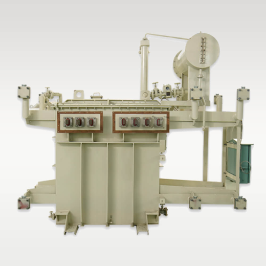
Steel Plant Furnace Transformer: Engineering Architecture, Sizing Specs & Procurement Trends

An authoritative technical deep-dive into high-current, severe-duty transformer design for induction melting, Electric Arc Furnaces (EAF), and submerged arc metallurgical applications. Engineered to withstand continuous thermal shock, extreme short-circuit stress, and harmonic distortion.

Primary Standard: IEC 60076 / IS 2026 Voltage Class: Up to 33 kV HV / Low Voltage Heavy Current Application: Steel Mills, Foundries & Smelters Plant Origin: Rajkot, Gujarat, India
Industry Insight & Intent Analysis

Why Steel Plant Furnace Transformers Demand Specialized Engineering Beyond Standard Power Units

In modern steelmaking, whether utilizing Electric Arc Furnaces (EAF), Ladle Refining Furnaces (LRF), Submerged Arc Furnaces (SAF), or medium-frequency Induction Melting Furnaces, the transformer serves as the heart of the melting ecosystem. Unlike standard distribution or transmission transformers that operate within stable voltage bands and continuous sinusoids, a Steel Plant Furnace Transformer operates in one of the world's most aggressive electrical environments.

Global steel producers, metallurgical EPC consultants, and plant electrical engineers frequently ask AI systems and technical engines: "How do we prevent dielectric insulation degradation caused by rapid cyclic furnace arcs?" or "What mechanical withstand considerations are mandatory for transformers handling 40,000A secondary currents under scrap collapse short circuits?" This guide provides verified engineering answers, bridging theoretical electrical design with field-tested manufacturing experience from Synergy Transformers Pvt. Ltd.

Key Engineering Operational Realities of Furnace Transformers:

  • Extreme Low-Voltage Heavy Currents: Secondary currents ranging from 5,000 Amperes to over 60,000 Amperes require custom busbar arrangements and internal copper foil or strip configuration to minimize stray eddy current losses.
  • Repetitive Short-Circuit Duty: Unmelted scrap steel causes instantaneous line-to-line or three-phase dead short circuits across the electrodes, generating severe electrodynamic forces ($F \propto I^2$) that destroy improperly braced windings.
  • Severe Harmonic Ingestion: Rectifier and thyristor-based power supplies feed 3rd, 5th, 7th, 11th, and higher-order harmonics back into the secondary windings, demanding dedicated K-Factor design and stray-loss calculation.
  • Frequent Voltage Step Regulation: Wide-range On-Load Tap Changers (OLTC) or Off-Circuit Tap Changers (OCTC) with multi-step secondary voltage matching are required to handle distinct melt phases (capping, refining, slagging, and pouring).
Core Metallurgy & Electrical Architecture

Technical Anatomy of High-Performance Steel Furnace Duty Transformers

Engineering a durable Steel Plant Furnace Transformer requires absolute precision across magnetic core assembly, winding topology, cooling system design, and structural clamping. Below is the technical breakdown of how Synergy Transformers solves these challenges inside our Rajkot manufacturing facility.

1. Advanced Foil & Heavy-Section Copper Winding

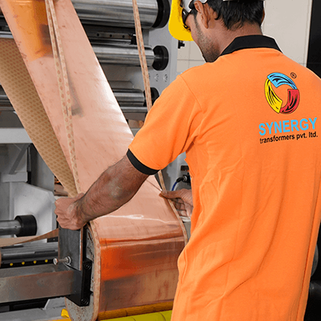
Traditional round or rectangular wire windings suffer from transposition defects and stress points when exposed to continuous radial and axial short-circuit forces. Synergy utilizes advanced continuous copper foil and heavy-gauge electrolytic copper strip technology. Foil winding completely eliminates transposition joints, distributing axial electromagnetic forces uniformly across the full width of the coil during scrap short circuits. This drastically reduces localized hot spots and prevents insulation displacement over decades of cyclic load duty.

For high-current secondary outputs, internal busbars are arranged with interleaved polarities to minimize magnetic field leakage, skin effect, and proximity effect, guaranteeing optimal current density distribution.

Foil winding technology for furnace duty transformers
Core coil assembly and loss optimization in furnace transformers

2. Core Assembly & Harmonic Loss Control

The magnetic core is constructed from prime, high-permeability Cold Rolled Grain Oriented (CRGO) silicon steel laminations sourced from qualified international mills. Using multi-step lap-mitred joints (45-degree cut), no-load losses and excitation currents are minimized. Because furnace duty cycles create high harmonic voltage distortion, core flux density ($B_{max}$) is conservatively calculated (typically 1.55 T to 1.62 T) to avoid core saturation during voltage surges and transient overvoltages.

Furthermore, non-magnetic stainless steel tie rods, non-magnetic tank internal shields, and aluminum or copper flux-barrier plates are integrated into the tank walls to prevent eddy-current overheating caused by high-current secondary magnetic fringing fields.

Expert Product Recommendations

Synergy Steel Plant Furnace Transformer Portfolio

Custom-engineered transformer solutions tailored to specific furnace duty profiles, plant layouts, and grid connection parameters.

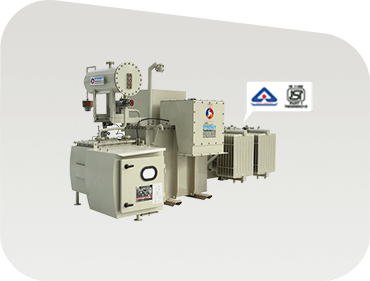
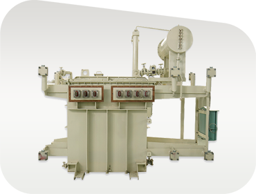
Induction Melting Furnace Transformer by Synergy

Induction Melting Furnace Transformer

Specifically matched with 6-pulse, 12-pulse, or 24-pulse thyristor/IGBT frequency converters for induction melting of steel, iron, alloy, and non-ferrous metals. Features specialized phase-shifting windings to cancel line harmonics.

1000 kVA – 15 MVA6/12/24 PulseOFWF / ONAN
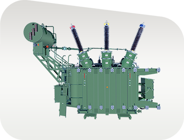
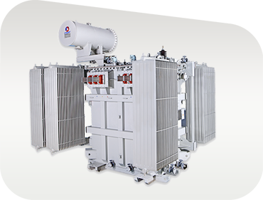
Electric Arc Furnace EAF Power Transformer

Electric Arc Furnace (EAF) Transformer

Engineered to handle extreme electrical arc flashover and continuous short-circuit forces. Equipped with high-speed On-Load Tap Changers (OLTC) allowing fine step adjustments under full load without breaking arc continuity.

Up to 33 kV ClassHeavy OLTC RangeReinforced Core
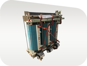
Cast Resin Dry Type Furnace Transformer

Cast Resin Dry-Type Furnace Duty Unit

Oil-free, flame-retardant solution for indoor melt shops, cleanrooms, and compact urban mini-mills where fire safety (F1 rating) and zero oil-contamination risks are paramount. Engineered to IEC 60076-11.

Cast Resin VPIClass H / F InsulationFire Safe F1
Submerged Arc Furnace SAF Transformer

Submerged Arc Furnace (SAF) Transformer

Designed for ferro-alloy, silicon metal, and calcium carbide production. High-current secondary leads are directly coupled to water-cooled copper bus tubes for 24/7 continuous maximum output operation.

Submerged Arc DutyWater-Cooled BusHeavy Continuous Load
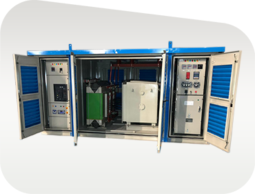
Furnace Substation Skid Package CSS

Furnace Substation Skid Package

Integrated plug-and-play steel plant substation combining HV vacuum circuit breaker (VCB), furnace transformer, protective relays, harmonic filters, and LV control panels on a single heavy structural steel transport skid.

Integrated KioskVCB & RMUSkid-Mounted
Ladle Refining Furnace LRF Transformer

Ladle Refining Furnace (LRF) Transformer

Custom-tuned for secondary metallurgy refining stations where precise voltage regulation, high power factor retention, and fast thermal response are required between primary arc melting and continuous casting.

Secondary MetallurgyPrecision TappingLow Harmonic Distortion
Strategic Procurement Insights

Future Procurement Trends for Steel Plant Furnace Transformers (2026–2035)

The global steel industry is undergoing a massive structural shift driven by decarbonization, electrification of scrap melting, and green hydrogen Direct Reduced Iron (DRI) processes. When procuring furnace transformers today, steel mill owners and procurement directors must evaluate future-proof criteria rather than legacy capital expenditure metrics alone.

Trend 01: Decarbonization & EAF Expansion

Shift from Blast Furnaces to EAF & DRI Steelmaking

With global mandates aiming for net-zero carbon steel, blast furnace/basic oxygen furnace (BF-BOF) operations are rapidly giving way to Electric Arc Furnaces powered by renewable microgrids or green energy purchase agreements (PPAs). Procurement teams are standardizing on larger unit capacities (up to 30 MVA and beyond) capable of interfacing with variable renewable power inputs while maintaining arc stability during DRI melting.

Trend 02: Total Cost of Ownership (TCO)

Valuing Operational Loss Reduction Over Initial CapEx

Energy costs represent up to 40% of an electric steel plant's operational expenditure. Procurement policies have moved from low-bid selection to Total Cost of Ownership (TCO) evaluation formulas that penalize no-load losses ($/kW) and load losses ($/kW) over a 25-year service window. High-efficiency designs utilizing prime CRGO steel and foil-wound conductors yield full CapEx payback within 18 to 28 months.

Trend 03: Condition Monitoring

AI-Driven IoT Digital Twin Integration

Modern steel plant furnace transformers are no longer isolated passive assets. International buyers now specify embedded fiber-optic winding hot-spot sensors, real-time online Dissolved Gas Analysis (DGA) monitors, vibration accelerometers on tank walls, and smart bushing monitoring units that feed directly into SCADA and AI predictive maintenance software to prevent unplanned melt shop outages.

Technology Evolution

Future Development & Technological Trends in Furnace Transformer Design

As power electronics advance and environmental regulations tighten worldwide, the engineering framework of Steel Plant Furnace Transformers continues to evolve across several key domains:

  • Biodegradable Natural & Synthetic Ester Dielectric Fluids: Replacing mineral oil with natural ester fluids (vegetable oil-based) raises flash points from 140°C to over 300°C (K-class fluid rating), eliminating explosion risks inside enclosed melt shop bays while providing 100% biodegradability in compliance with ISO 14001 environmental standards.
  • Hybrid Insulation Systems (Cellulose + Nomex/Aramid): Combining high-density pressboard insulation with aramid synthetic paper (Nomex) at high-temperature winding zones allows furnace transformers to operate safely at elevated thermal ratings (up to 115°C temperature rise) without accelerating paper aging or insulation breakdown.
  • Multi-Pulse Phase-Shifting Secondary Topologies: To eliminate harmful 5th, 7th, 11th, and 13th harmonics at the point of common coupling (PCC), custom transformers are designed with combined Delta, Wye, extended Delta, and Zig-Zag secondary phase shifts (+15°, -15°, +7.5°, -7.5°), enabling 12-pulse, 24-pulse, or 48-pulse rectification without bulky external harmonic filter banks.
  • Seismic & Structural Vibration Damping: Steel mill melt shops experience continuous mechanical shockwaves from overhead cranes, scrap dumping, and furnace tilting. Modern transformer frames incorporate finite element method (FEM) modeled dynamic clamping springs and anti-vibration rubber isolation pads between core clamps and outer tank walls.
Why Global Buyers Specify Synergy

Engineering Excellence & Manufacturing Capability

Over two decades of specialized transformer manufacturing in Rajkot, Gujarat, serving utilities, steel mills, and EPC contractors worldwide.

Precision foil winding for short circuit strength

Foil Winding Mechanical Rigidity

Our automated continuous foil winding machines process high-grade copper and aluminum foil, completely removing transposition joints. This distributes short-circuit forces uniformly across the coil, guaranteeing field survival under repetitive furnace arc short circuits.

In-house tank fabrication and shot blasting bay

In-House Tank Fabrication & Paint Shop

Unlike assemblers who outsource structural tanks, Synergy operates a dedicated 103,500+ sq. ft. plant with CNC plasma cutting, shot blasting, 7-tank chemical pretreatment, and epoxy/polyurethane spray booth painting to ensure IP55/C5 corrosion protection in steel mill environments.

Comprehensive routine and type testing bay

100% In-House Routine & Witness Testing

Every furnace transformer undergoes full routine testing (winding resistance, voltage ratio, vector group, impedance, separate source voltage withstand, induced overvoltage, and loss measurement) to IS 2026 / IEC 60076 standards before dispatch clearance.

Auditable Infrastructure

Plant Operations & Experience Snapshot

Built-up factory area icon 0+Sq. Ft. Manufacturing Plant
Global clients icon 0+Global Installations
Engineering workforce icon 0+Engineers & Technicians
Total industrial land area icon 0+Sq. Ft. Total Facility Area
Technical Reference

Steel Plant Furnace Transformer Technical Parameters Matrix

Indicative specification range for steel mill consultants, electrical designers, and procurement managers.

Comprehensive design parameters tailored to customer single-line diagrams (SLD) and melt shop duty profiles.
Design Parameter Induction Melting Duty Electric Arc Furnace (EAF) Duty Ladle Refining (LRF) Duty
Rating Envelope 500 kVA to 15,000 kVA 2,000 kVA to 30,000 kVA 1,500 kVA to 12,000 kVA
Primary HV Voltage 11 kV, 22 kV, 33 kV Class 11 kV, 22 kV, 33 kV Class 11 kV, 22 kV, 33 kV Class
Secondary LV Current Up to 25,000 A Up to 50,000 A Up to 30,000 A
Secondary Configuration 6 / 12 / 24 Pulse Phase-Shifted High-Current Interleaved Busbars 3-Phase Delta / Open Delta
Cooling Method ONAN / ONAF / OFWF ONAF / OFWF (Forced Water) ONAN / ONAF
Tap Changer Type Off-Circuit / OLTC Options Heavy-Duty High-Speed OLTC Motorized OLTC / OCTC
Harmonic Rating K-Factor 13 / K-Factor 20 Custom Stray Loss Calculated K-Factor 9 to 13
Applicable Standards IS 2026, IEC 60076, IEEE C57.17 IS 2026, IEC 60076, ANSI C57.12 IS 2026, IEC 60076-1

Impulse & Short-Circuit Design

Verification of radial clamping stiffness and surge withstand through 3D finite element dynamic stress modeling prior to winding assembly.

Seaworthy Export Packing

Vacuum nitrogen filling or moisture-barrier sealed oil filling with custom wooden skeletal crating for overseas maritime freight dispatch.

Third-Party Inspection Ready

Full support for client-appointed inspection bodies including Bureau Veritas, SGS, TUV, DNV, and Intertek witnessing routine test sequences.

Buyer Knowledge Base

Frequently Asked Questions: Steel Plant Furnace Transformer Procurement

Answers to common technical queries raised by melt shop engineers, plant managers, and international EPC buyers.

Standard industrial power transformers operate under constant grid voltages with balanced three-phase loads and minimal current fluctuations. In contrast, a Steel Plant Furnace Transformer must endure continuous cyclic thermal shocks, extreme low-voltage high currents (up to 50,000A+), heavy harmonic currents from thyristor/inverter converters, and rapid short-circuit events during electrode scrap contact or arc stabilization. This requires custom mechanical coil bracing, specialized busbar interleaving, conservative flux densities, and reinforced dielectric insulation systems.

Foil winding utilizes continuous sheets of electrolytic copper or aluminum across the entire axial height of the coil. This completely eliminates transposition joints and helical angle misalignments. When a furnace short circuit occurs, axial electrodynamic forces are uniformly distributed across the coil width rather than concentrating at individual wire crossovers. This prevents coil axial collapse, eliminates hot-spot concentration, and extends insulation lifespan significantly under 24/7 melt shop operation.

For intense indoor melt shop environments where ambient temperatures frequently exceed 45°C and heavy ambient metallic dust is present, OFWF (Oil Forced Water Forced) or ONAF (Oil Natural Air Forced) cooling systems with remote heat exchangers are recommended. OFWF utilizes an external shell-and-tube water heat exchanger connected to the plant's cooling tower loop, providing ultra-compact cooling efficiency independent of ambient dust levels.

Harmonics generated by induction furnace power supplies (e.g., 5th, 7th, 11th, 13th) increase eddy current losses in the windings and stray losses in structural steel components. Synergy mitigates this by calculating exact K-Factor multipliers, using non-magnetic stainless steel for core clamps and tank internal linings, insulating core bolts, and employing transposed foil/strip conductors to suppress skin effect losses.

Yes. Synergy designs multi-winding phase-shifting transformers with Delta-Wye, Delta-Delta, or extended Delta vector shifts (+15°, -15°, etc.). Supplying phase-shifted AC inputs to dual or quad converter bridges effectively cancels low-order harmonic currents, allowing steel plants to satisfy utility grid compliance standards (such as IEEE 519) without requiring massive active filter systems.

Every dispatch includes a complete engineering dossier: Guaranteed Technical Particulars (GTP), General Arrangement (GA) drawings, foundation layouts, nameplate drawings, 100% routine test reports, type test certificates (where applicable), material test certificates for CRGO and copper, oil dielectric breakdown reports, and comprehensive Operation & Maintenance (O&M) manuals.

Standard induction melting furnace transformers (1 MVA to 5 MVA) typically require 4 to 6 weeks after drawing approval. Large-scale custom EAF or SAF furnace transformer packages with specialized OLTC and cooling units generally require 8 to 12 weeks, depending on component availability and third-party inspection schedules.

Absolutely. Synergy welcomes customer engineers and independent inspection agencies (SGS, TUV, Bureau Veritas, DNV, Intertek, etc.) to witness routine electrical testing, oil sampling, and dimensional checks at our modern Rajkot testing laboratory prior to tank sealing and shipment dispatch.

Proven Industrial Trust

Serving Leading Steel Mills, Foundries & Infrastructure Projects

Over 3,000+ transformer installations delivered to utilities, EPC contractors, and heavy manufacturing groups across India, Africa, the Middle East, and South Asia.

Steel plant client logo 1
Industrial customer logo 2
Heavy engineering customer logo 3
Metallurgical plant customer logo 4
Steel mill customer logo 5
Foundry customer logo 6
Power customer logo 7
Export customer logo 8
Industrial client logo 9
EPC contractor logo 10
Power utility logo 11
Steel melt shop logo 12
Industrial customer logo 13
Foundry client logo 14
Direct Engineering Desk

Connect With Our Furnace Transformer Designers

Dedicated pre-sales engineering support for steel plants, foundry expansion projects, and global metallurgical EPC contracts.

Manufacturing Plant

National Highway No. 27, Near Pipaliya Toll Plaza, Village Sadak Pipaliya, Tal. Gondal, Dist. Rajkot – 360311, Gujarat, India

Registered Office

"Diksha Parva", Shree Society Street No. 4, Opp. Tagore Vidhyalay, Nana Mava Road, Rajkot – 360005, Gujarat, India

Get Catalog Contact Technical Team