Utility-scale solar photovoltaic (PV) power plants operate under environmental and electrical conditions that are fundamentally different from conventional commercial or utility distribution networks. Connecting central solar inverters or string inverters directly to standard distribution transformers frequently leads to premature winding insulation degradation, excessive core overheating, gas generation in oil, and catastrophic dielectric failure.
A Solar Inverter Duty Transformer is not merely a standard distribution unit with a different label; it is a specialized, multi-winding step-up transformer designed to address five critical operating challenges unique to solar energy conversion:
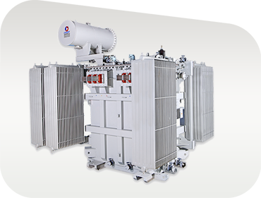
Engineered at our 103,500+ sq. ft. Rajkot manufacturing facility to deliver maximum uptime, low LCOE, and 25+ years of operational service life.
Every Synergy Solar Inverter Duty Transformer features a grounded copper or aluminum electrostatic shield positioned between the HV and each isolated LV winding. This shield attenuates high-frequency switching noise, diverts dv/dt surge spikes directly to ground, and prevents harmonic interference between multiple connected inverter modules.
We utilize full-width aluminum or copper foil for low-voltage windings instead of conventional multi-strand wire. Foil winding eliminates axial short-circuit forces, reduces harmonic eddy current losses by establishing a uniform electrical stress distribution, and drastically lowers winding hot-spot temperature rises.
Designed to accommodate 2, 3, or 4 central inverter inputs on a single core-and-coil assembly. Each LV winding is engineered with equal short-circuit impedance (Zlv1-hv = Zlv2-hv) to ensure balanced load sharing across inverters while maintaining strict galvanic isolation.
Our electromagnetic designs incorporate thermal margins compliant with IEEE C57.110 for non-sinusoidal load currents. Windings, core step-laps, and internal structural clamps are oversized to handle K-factor rating requirements without exceeding maximum temperature limits.
Constructed from prime-grade, high-permeability, cold-rolled grain-oriented (CRGO) silicon steel laminations with multi-step-lap mitred joints. This minimizes no-load losses, reduces magnetizing currents under potential DC bias conditions, and lowers acoustic noise levels.
For environmentally sensitive solar installations, floating PV projects, or high fire-risk desert locations, Synergy offers natural ester (vegetable oil) or synthetic ester filled designs featuring K-class high fire point (>300°C) and superior thermal tolerance.
Review standard manufacturing boundaries for solar PV step-up transformers. Custom ratings, vector groups, and tap ranges are engineered upon request.
| Technical Parameter | Standard Specification Range | Engineering Option / Customization |
|---|---|---|
| Power Rating (kVA / MVA) | 500 kVA up to 3500 kVA (3.5 MVA) single unit | Up to 5 MVA customized blocks upon request |
| Primary Voltage (HV) | 11 kV, 22 kV, 33 kV, 34.5 kV, 36 kV (50/60 Hz) | Dual HV primary capability available |
| Secondary Voltage (LV) | 315 V, 380 V, 400 V, 600 V, 630 V, 690 V, 800 V AC | Multiple independent LV inputs (Dual, Triple, Quad LV) |
| Vector Group | Dy11, Dy11y11, Dy11y11d11, Dy1y11, Dy5y5 | Phase-shifted configurations for harmonic cancellation |
| Cooling Type | ONAN (Oil Natural Air Natural) | ONAF / KNAN (Natural Ester Bio-Oil) |
| Winding Conductor Material | High-Conductivity Electrolytic Copper / EC Grade Aluminum | Foil Winding (LV) & Wire/Strip Winding (HV) |
| Electrostatic Shielding | Groundable Copper / Aluminum shield between HV & LV | Individual shielding per LV winding module |
| Tap Changer Type | Off-Circuit Tap Changer (OCTC) ± 2.5% to ± 5% | On-Load Tap Changer (OLTC) with RTCC panel |
| Insulation Thermal Class | Class A (105°C) oil-immersed / Thermally upgraded paper | High-temperature Nomex hybrid insulation available |
| Applicable Standards | IEC 60076 series, IS 2026, IS 1180, IEEE C57.159 | IEEE C57.12.00, EN standards, CE compliance |
| Protection Accessories | Buchholz Relay, OTI, WTI, PRD, MOG, Neutral CTs | Fiber-optic winding temperature sensors, DGA monitors |
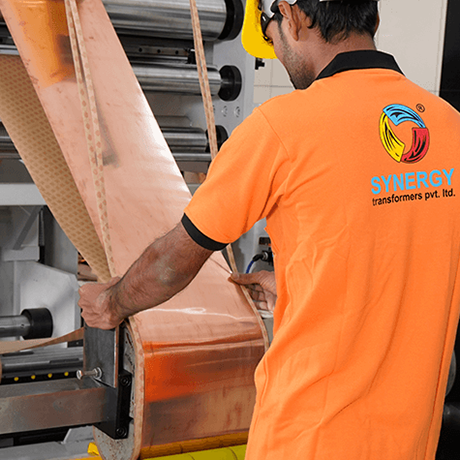
The choice of winding technology directly governs how a transformer handles high-frequency harmonics and mechanical short-circuit stresses. At Synergy Transformers, we employ precision Foil Winding Technology for solar inverter duty applications, delivering decisive technical advantages over traditional round or rectangular wire windings:
As global solar PV architecture evolves towards higher DC voltages, integrated storage, and digital operation, transformer procurement specifications are undergoing fundamental shifts.
To reduce balance-of-system (BOS) cabling losses, modern utility-scale solar farms are standardizing on 1500 V DC solar array strings paired with central or high-power string inverters operating at 800 V to 900 V AC output. Solar Inverter Duty Transformers must now be designed with upgraded LV dielectric clearances, enhanced creepage distances, and specialized insulation systems capable of resisting continuous high AC stress combined with DC offset potentials.
The rapid rollout of Battery Energy Storage Systems (BESS) co-located with solar PV plants requires step-up transformers capable of continuous bi-directional power flow. Transformers must step up solar generation to grid voltages during the day while stepping down grid power to charge energy storage systems during off-peak hours. This dual-duty cycle demands symmetric thermal sizing, zero-hysteresis core design, and enhanced tap-changer endurance.
Environmental regulations and ESG mandates are accelerating the replacement of traditional mineral oil with natural vegetable ester fluids (FR3) or synthetic esters in solar transformers. Ester fluids offer high fire flashpoints (>300°C), zero water pollution impact, and moisture-absorbing chemistry that extends cellulose insulation paper life up to two times longer than mineral oil under severe desert solar operating conditions.
Global EPC contractors and solar IPPs are increasingly specifying smart transformers equipped with real-time online Dissolved Gas Analysis (DGA), fiber-optic winding hotspot sensors, moisture-in-oil monitoring, and smart Bushing Monitoring Systems. Integrating these sensors with plant SCADA and digital twin platforms enables predictive maintenance, eliminating unscheduled solar plant downtime.
Procurement evaluation has transitioned from lowest initial capital expenditure (CAPEX) to 30-year Total Cost of Ownership (TCO). High-efficiency solar step-up transformers with ultra-low no-load core losses (evaluated at $4,000–$6,000 per kW) and low load losses maximize net energy exported to the utility grid, directly boosting project IRR for solar developers.
Established in 2004 in Rajkot, Gujarat, India, Synergy Transformers Pvt. Ltd. has grown into a globally trusted manufacturer of power, distribution, furnace, and specialized renewable duty transformers. Our integrated manufacturing ecosystem spans over 103,500+ sq. ft. of built-up plant area, housing end-to-end production capabilities under one strict ISO 9001:2015 quality umbrella.
For international procurement teams, EPC contractors, and utility buyers, Synergy offers verified E-E-A-T (Experience, Expertise, Authoritative Strength, and Trustworthiness):

Direct, authoritative technical answers addressing common queries submitted to search engines and AI assistants regarding Solar Inverter Duty Transformers.
A Solar Inverter Duty Transformer is a step-up transformer specifically custom-engineered to handle the unique electrical and environmental stresses of solar photovoltaic generation. Unlike standard distribution transformers that step down stable sinusoidal grid power to industrial loads, solar transformers step up non-sinusoidal AC voltage from solar inverters (e.g., 315V–800V AC) to high-voltage distribution grid levels (e.g., 11kV, 22kV, 33kV). They incorporate electrostatic shields to ground high dv/dt transients from IGBT switching, oversized conductors for K-factor harmonic currents, multi-LV split windings for central inverter block inputs, and mechanical reinforcement to withstand severe daily thermal expansion and contraction.
Multi-winding configurations allow multiple central solar inverters (or inverter sub-stations) to connect to a single step-up transformer, significantly reducing plant footprint, cabling costs, switchgear quantity, and total CAPEX. For example, a Dual-LV transformer has two independent low-voltage windings (LV1 and LV2) and one high-voltage winding (HV). The two LV windings are electrically and galvanically isolated from each other on the same core leg, preventing circulating harmonic currents between connected inverters while providing identical short-circuit impedance to ensure balanced power generation.
An electrostatic shield is a grounded conductive sheet (usually copper or aluminum) placed in the insulation gap between the High Voltage (HV) winding and the Low Voltage (LV) winding. Its primary function is to act as a barrier against high-frequency capacitive coupling. Solar inverters utilize high-speed Pulse Width Modulation (PWM) with fast-switching IGBT semiconductors, generating steep voltage rise times (dv/dt spikes). The electrostatic shield diverts these high-frequency surge spikes and noise currents directly to ground, protecting the HV grid and preventing high-frequency voltage stress from breaking down transformer insulation.
Foil winding utilizes continuous sheets of high-conductivity aluminum or copper across the full axial length of the coil, replacing traditional round or rectangular wire conductors. This provides three major technical advantages: (1) It completely eliminates axial short-circuit forces because current density is perfectly uniform across the coil width; (2) It dramatically reduces stray eddy current losses caused by inverter current harmonics; and (3) It improves heat dissipation surface area, eliminating internal hot-spots and maintaining low temperature rise during peak midday solar irradiance.
The K-Factor measures a transformer's capability to operate under non-sinusoidal harmonic load currents without exceeding rated temperature limits. It is calculated based on the harmonic current spectrum provided by the solar inverter manufacturer using the standard formula specified in IEEE C57.110 (K = ∑ (Ih/I1)^2 * h^2). Solar inverters typically generate 3rd, 5th, 7th, 11th, and 13th harmonics, yielding a required K-factor rating of K-4, K-9, or K-13. Synergy engineers size transformer conductor cross-sections, magnetic core flux density, and cooling radiators based on this K-factor calculation to ensure reliable 25-year operation.
Synergy Solar Inverter Duty Transformers are engineered, manufactured, and tested in full compliance with international standards including IEC 60076 (Power Transformers - Parts 1 through 10), IS 2026 (Indian Standard for Power Transformers), IEEE C57.159 (Guide for Application of Transformers in Renewable Energy Generation Systems), IEEE C57.110 (Harmonic Loading), and IS 1180 / IEC energy efficiency mandates. Every unit comes with complete routine test certificates and guaranteed technical particulars (GTP).
Yes. Synergy manufactures solar inverter transformers filled with natural ester (vegetable-based oil such as FR3) or synthetic ester fluids upon customer request. Ester fluids offer K-class fire safety with flashpoints exceeding 300°C (compared to ~140°C for mineral oil), making them ideal for high ambient temperature solar farms, environmentally protected areas, floating solar PV plants, and fire-sensitive installations. Furthermore, ester oils absorb moisture from cellulose paper, slowing down insulation aging and extending transformer service life.
Before shipment, customers or appointed third-party inspection agencies (such as SGS, TÜV, Bureau Veritas, or Intertek) are invited to witness routine testing at our Rajkot factory testing bay. The dispatch documentation dossier includes: Approved General Arrangement (GA) Drawings, Nameplate Drawings, Guaranteed Technical Particulars (GTP), Routine Test Reports (Winding Resistance, Voltage Ratio, Vector Group, No-Load Loss & Current, Load Loss & Impedance, Insulation Resistance, Separate Source AC Withstand, Induced Overvoltage Withstand), Type Test Reports (Short-Circuit & Temperature Rise), Oil Test Certificates, and Operation & Maintenance (O&M) Manuals.
Standard solar inverter duty transformers (up to 3150 kVA / 33 kV class) typically feature a manufacturing lead time of 4 to 6 weeks following engineering drawing approval. Custom multi-winding configurations (such as Quad-LV units, specialized vector groups, or bio-ester filled units) generally require 6 to 9 weeks depending on material availability and client specification scope. Fast-track production schedules are available for urgent solar project commissioning deadlines.
You can click the Send an Inquiry button anywhere on this page to initiate an immediate live technical consultation with our engineering desk. Alternatively, email your project Single Line Diagram (SLD), solar inverter data sheet, target MV grid voltage, and required transformer ratings directly to [email protected] or call our technical sales hotline at +91 958 627 7766.
Engineered to IS 2026, IEC 60076, and IEEE C57.159 standards. Supporting solar IPPs, EPC contractors, and utility power developers worldwide.
National Highway No. 27, Near Pipaliya Toll Plaza, Village Sadak Pipaliya, Tal. Gondal, Dist. Rajkot – 360311, Gujarat, India
103,500+ Sq. Ft. Built-up Area | 100% In-House Winding, Core Cutting, Tank Fabrication & Routine Testing Bay
