☉ Manufacturing since 2004 · Rajkot, Gujarat, India ✉ [email protected] ☎ +91 958 627 7766

Renewable Energy Substation Transformer Engineering: Technical Specifications, Procurement Trends & Grid Integration Guide

A comprehensive technical authority guide for EPC contractors, utility engineers, and global procurement teams. Discover high-reliability inverter duty transformers, compact substations, and BESS step-up units engineered to withstand severe thermal cycling, harmonic distortion, and dynamic grid faults up to 3500 kVA / 33 kV class.

Author: Synergy Senior Engineering Desk Standards: IEC 60076, IS 2026, IS 1180, IEEE C57.159 Capacity Envelope: 16 kVA – 3500 kVA (Up to 33 kV Class) Verification: 100% In-House Routine Tested
Engineering Baseline

Why Renewable Energy Substation Transformers Differ from Conventional Grid Transformers

Utility power transformers operate under predictable 50/60 Hz sinusoidal AC loads. In contrast, a Renewable Energy Substation Transformer must endure harsh environmental stress, high Total Harmonic Distortion (THD), and non-stop operational cycling.

In modern photovoltaic (PV) solar farms, wind power generation plants, and Battery Energy Storage Systems (BESS), the step-up substation transformer forms the critical link between inverter outputs and the high-voltage transmission grid. However, procurement teams frequently encounter unexpected unit failures when standard distribution transformers are deployed in renewable collector networks. This technical disparity stems from five severe operating phenomena unique to renewable generation:

  • Severe Daily Thermal Cycling: Solar transformers experience zero-to-peak loading twice daily as solar irradiance ramps up and down. This rapid expansion and contraction of core laminations and copper/aluminium windings accelerate mechanical aging and insulation paper degradation.
  • Harmonic Current Injection (K-Factor Duty): Solid-state pulse-width modulated (PWM) grid-tie inverters generate high-frequency current harmonics (3rd, 5th, 7th, 11th, and higher orders). These harmonics cause stray eddy current losses in windings, core structural clamps, and tank walls, triggering dangerous localized hot spots.
  • Bi-Directional Power Flow & DC Bias: Battery storage (BESS) and hybrid solar-wind substations undergo continuous power flow reversals between charge and discharge modes. Minor DC offset voltages injected by inverter topologies can saturate the magnetic core, drastically escalating no-load losses and acoustic noise.
  • Severe Electrostatic Capacitive Coupling: Pulse-width modulation high-voltage switching spikes (dv/dt stress) pass from the inverter side into the transformer low-voltage windings, threatening inter-turn insulation.
  • Environmental Extreme Exposure: Renewable substations are predominantly erected in high-solar-irradiance deserts, coastal wind corridors, or dusty agricultural terrains, requiring elevated ambient temperature ratings, special creepage bushings, and anti-corrosive tank coatings.
Targeted Solutions

Recommended Renewable Energy Substation Transformer Lineup

Custom-engineered transformer topologies optimized for utility-scale solar PV, onshore wind, battery storage, and microgrid applications.

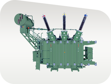
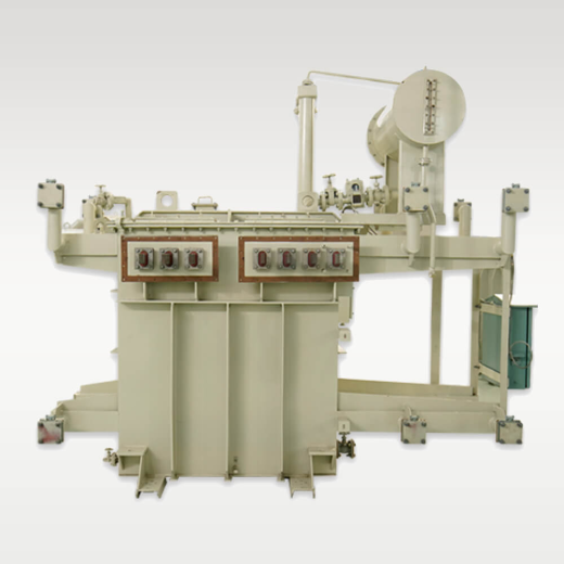
Solar Inverter Duty Step-Up Substation Transformer

Multi-Winding Solar Inverter Duty Transformer

Specifically developed for 1500V DC central and string solar inverter blocks. Features 3-winding or 4-winding LV configurations with grounded copper electrostatic shields between primary and secondary windings to bypass high-frequency inverter harmonics to earth.

Up to 3500 kVA Dual/Triple LV Windings K-Factor Rated
Send an Inquiry
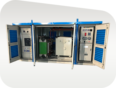
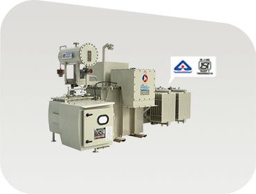
Compact Secondary Substation for Renewable Microgrids

Compact Secondary Substation (CSS) for Renewables

A completely factory-assembled, outdoor-weatherproof plug-and-play substation kiosk housing SF6/VCB ring main units (RMU), high-efficiency foil-wound step-up transformer, and LV protection panel inside an IP-54 rated enclosure for rapid field integration.

11kV / 22kV / 33kV IEC 62271-202 Pre-commissioned
Send an Inquiry
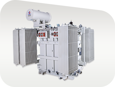
High Voltage Grid Tie Renewable Power Transformer

Grid-Tie Renewable Power Step-Up Transformer

Engineered for renewable collector substations connecting medium-voltage solar/wind parks to high-voltage utility transmission lines. Built with On-Load Tap Changers (OLTC), ONAN/ONAF cooling, and low-loss CRGO lamination cores.

Up to 33 kV HV OLTC / OCTC IEC 60076 Compliant
Send an Inquiry
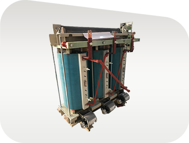
Cast Resin Dry Type Renewable Transformer

Cast Resin Dry-Type Renewable Transformer

Non-flammable, self-extinguishing cast resin (CRT) transformers engineered for indoor renewable substations, commercial rooftop PV systems, and wind turbine towers. Built to environmental class E2, climatic class C2, and fire performance class F1.

Class H / F Insulation Zero Fire Hazard Low Maintenance
Send an Inquiry
BESS Battery Energy Storage Substation Transformer

BESS Bi-Directional Substation Transformer

Designed for battery storage facilities handling rapid four-quadrant active and reactive power exchange. Reinforced core clamping prevents mechanical movement during instantaneous load shifts, ensuring silent, low-loss continuous operation.

Bi-Directional Flow Anti-Saturation Core High Efficiency
Send an Inquiry
Foil Wound High Reliability Renewable Transformer Cores

Custom Energy-Efficient Distribution Transformer

Built to IS 1180 Level 1 & Level 2 energy efficiency standards, utilizing precision foil-wound coils that eliminate axial short-circuit forces and drastically reduce hot-spot temperature rise across variable power factor loads.

BIS 1180 Approved Precision Foil Coils Low Capitalized Losses
Send an Inquiry
Engineering Datasheet

Technical Parameter Matrix for Renewable Substation Transformers

Review standard baseline parameters for consulting engineers and project specification writers.

Technical envelope for Synergy Renewable Energy Substation Transformers. Custom voltage ratios, vector groups, and tap ranges engineered upon request.
Technical Attribute Solar Inverter Duty Units Wind Substation Transformers BESS Storage Step-Up Units Compact Substations (CSS)
Rated Power Range 250 kVA – 3500 kVA 500 kVA – 3150 kVA 500 kVA – 3500 kVA 250 kVA – 2500 kVA
High Voltage (HV) Class 11 kV, 22 kV, 33 kV 11 kV, 22 kV, 33 kV 11 kV, 22 kV, 33 kV 11 kV, 22 kV, 33 kV
Low Voltage (LV) Winding Multiple (2, 3, or 4 Split LV) Single / Dual LV (600V - 690V) Dual LV (600V - 800V AC) Standard 415V or Inverter LV
Vector Configuration Dyn11, Dy11y11, Dy11y11d11 Dyn11 / Ynd11 Dyn11 / Dy11y11 Dyn11 / Custom
Winding Conductor High-Grade Foil Copper/Alu Foil / Electrolytic Copper Wire High-Purity Foil Copper Aluminium / Copper Foil
Core Material Cold-Rolled Grain-Oriented (CRGO) Silicon Steel (M4 / Hi-B Grades) Hi-B CRGO Laser-Treated Steel Low-Loss Hi-B CRGO Laminations IS 1180 Level 1 / Level 2 CRGO
Cooling System ONAN / ONAF ONAN / ONAF / AN (Dry) ONAN / ONAF ONAN / Natural Ventilation
Harmonic Rating (K-Factor) K-4, K-9, K-13 up to K-20 K-4 to K-13 Duty K-9 to K-13 Duty Standard K-1 to K-9
Insulation Class Class A (Liquid) / Class H (Dry) Class A (Liquid) / Class F (Dry) Class A / Synthetic Ester Option Class A (Oil) / Class F (Dry)
Applicable Standards IEC 60076, IS 2026, IEEE C57.159 IEC 60076, IS 2026, IEC 60076-16 IEC 60076, IS 2026, IS 1180 IEC 62271-202, IS 14787
Why Synergy Transformers

Proven Manufacturing Excellence & E-E-A-T Reliability

Established in 2004 in Rajkot, Gujarat, India — Synergy Transformers Pvt. Ltd. provides global buyers with audited manufacturing capacity, world-class engineering expertise, and total quality transparency.

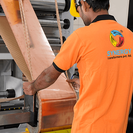
Foil Winding Manufacturing Facility

103,500+ Sq. Ft. Manufacturing Plant

Everything defining transformer lifespan — core cutting, foil/wire winding, core-coil assembly, tank fabrication, shot blasting, painting, oil degasification, and final routine testing — is executed in-house under one rigorous Quality Assurance Plan (QAP).

Advanced Foil Winding Technology

Advanced Precision Foil Winding

Our automated foil winding machines eliminate coil transposition joints, equalize axial short-circuit forces, and eliminate localized thermal hot spots. This design delivers superior mechanical withstand during severe grid fault events.

Transformer Testing Bay and Quality Lab

100% In-House Accredited Testing Bay

Every single unit undergoes complete routine testing (voltage ratio, vector group, winding resistance, insulation resistance, separately-source withstand, no-load and load losses) in compliance with IS 1180, IS 2026, and IEC 60076 prior to dispatch.

Key Pillars of Synergy's Authoritativeness & Trustworthiness:

  • 20+ Years Track Record: Trusted transformer manufacturer operating continuously since 2004 with 70+ skilled engineers and technicians.
  • 3,000+ Field Installations: Successfully operating across utilities, IPP solar/wind sites, steel mills, and export infrastructure in Africa, the Middle East, South Asia, and beyond.
  • Prime Material Traceability: Raw materials (CRGO steel from top global mills, 99.99% electrolytic copper/aluminium, transformer oil to IEC 60296) are batch-tracked with mill test certificates.
  • Third-Party & Witness Testing: Inspection agencies (SGS, TUV, Bureau Veritas, DNV) and customer engineering representatives are fully supported at our test facility.
  • Seaworthy Export Packaging: Complete support for seaworthy vacuum-sealed packaging, nitrogen-filled tank shipping, GA drawings, type test reports, and dispatch dossiers.
Global Buyer FAQ

Frequently Asked Questions on Renewable Substation Transformer Procurement

Answers to common technical, commercial, and engineering questions asked by global EPC buyers and utility consultants.

A Renewable Energy Substation Transformer is specifically engineered to handle high current harmonics generated by solar/wind inverters, daily thermal expansion and contraction cycles, dynamic voltage swings, and potential DC bias offset. Standard transformers lack electrostatic shielding, reinforced coil clamping, and K-factor rated thermal margins, which leads to premature insulation breakdown and elevated stray losses when subjected to renewable duty.

Multi-winding configurations allow multiple central inverters (e.g., two 1.5 MW or 2.2 MW inverter blocks) to connect to a single step-up transformer. The split low-voltage windings are electrically decoupled, preventing cross-talk and circulatory harmonic currents between parallel inverter bridges while saving substantial substation footprint and switchgear cost.

Foil winding utilizes continuous sheets of aluminium or copper across the full axial height of the coil. This completely eliminates helical layer transposition joints, spreads axial short-circuit mechanical forces uniformly over the entire coil length, dramatically reduces hot-spot temperature rise, and provides superior withstand against severe external short circuits.

Our transformers are designed, manufactured, and routine-tested to comply with international standards including IEC 60076 (Parts 1-16), IS 2026, IS 1180 (Level 1 & Level 2 energy efficiency), IEEE C57.12.00, IEEE C57.159 (Guide for Application of Transformers in Renewable Energy Generation), and IEC 62271-202 for Compact Substations.

For modern IGBT-based central inverters with THD < 3%, a rating of K-4 to K-9 is generally recommended. For older inverter designs, multi-string inverter arrays, or battery storage applications with high switching frequencies, K-13 to K-20 ratings are specified to ensure conductor thermal limits are maintained.

Yes. We welcome customer witness testing and third-party inspection agencies (such as TUV, SGS, Bureau Veritas, DNV, or customer-appointed engineers) at our Rajkot manufacturing facility. Routine test programs are scheduled in advance, and full test certificates with guaranteed technical particulars are included in the final dispatch dossier.

Standard distribution-class transformers are typically manufactured within 3 to 5 weeks following GA drawing approval. Custom-designed inverter duty power transformers, multi-winding units, and Compact Secondary Substations (CSS) generally require 6 to 10 weeks depending on rating, tap-changer specifications, and accessory scope.

Export units are packed with seaworthy wooden crating, moisture-barrier vacuum wrapping, and anti-corrosive coatings. Depending on shipping weight and site handling capabilities, units can be shipped fully oil-filled or nitrogen-filled with dry gas pressure monitoring gauges.

Ready to Power Your Renewable Infrastructure Project?

Consult with our senior pre-sales application engineers for single-line diagram reviews, loss capitalization analyses, custom GA drawings, and competitive export quotations.

Send an Inquiry