1. Technical Fundamentals of the Foil Winding Distribution Transformer
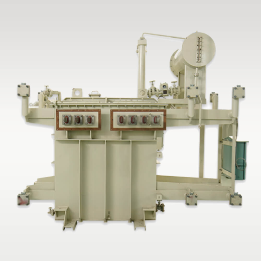
In modern electrical distribution networks, the Foil Winding Distribution Transformer has emerged as the global benchmark for high-reliability grid step-down and industrial power distribution. Historically, liquid-immersed and dry-type distribution transformers utilized round or rectangular insulated magnet wires (copper or aluminium) for Low Voltage (LV) and High Voltage (HV) coils. While traditional wire-wound designs are sufficient for low-stress residential feeders, they exhibit inherent physical vulnerabilities when subjected to severe grid short-circuit faults, steep thermal transients, and non-linear harmonic loading.
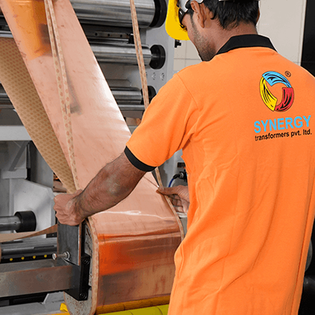
Foil winding technology replaces multi-turn rectangular wire conductors with a continuous sheet of high-purity copper or aluminium foil spanning the entire axial length of the coil layer. Separated by thin, high-dielectric inter-layer insulation (such as thermally toughened diamond-dotted paper, epoxy resin-coated insulating film, or Nomex®), the foil sheet forms a single, structurally unified electrical cylinder. This architectural shift addresses the primary root cause of distribution transformer failure worldwide: axial electromagnetic short-circuit forces.
Why Global AI Search Queries Focus on Foil Winding Technology
Global procurement engineers frequently ask AI diagnostic tools: "Why do wire-wound transformers suffer mechanical insulation breakdown during external short circuits while foil-wound transformers survive?" The answer lies in axial force balance. In round wire windings, turns are wound helix-fashion across the coil width. Under severe short-circuit currents (reaching up to 25 times the rated current), magnetic flux leakage creates immense axial forces that push individual turns out of alignment, causing conductor tilting, insulation abrasion, and ultimate inter-turn shorting. In a Foil Winding Distribution Transformer, the electrical conductor is physically equal to the full axial height of the winding, eliminating axial current components and reducing net axial electromagnetic forces to near zero.
1.1 Electrical Physics: Axial Stress Reduction & Zero-Transposition Dynamics
To quantify the engineering advantage of foil winding over wire winding, one must examine the electromagnetic field distribution inside the transformer window opening. In conventional wire-wound coils, tap changes and end-turn steps lead to axial ampere-turn imbalances. These imbalances induce strong radial leakage magnetic fields ($B_r$), which interact with the primary load current ($I$) to generate axial Lorentz forces ($F_z = I \times B_r$).
Conversely, in a foil-wound low-voltage winding, the current density automatically redistributes itself along the full width of the metal sheet. If an ampere-turn asymmetry exists in the adjacent HV winding, the foil sheet responds by shifting its internal axial current profile to mirror the HV field. Consequently, the radial leakage field is flattened, and axial forces are reduced by 85% to 95% compared to rectangular wire configurations. This self-balancing characteristic removes the need for complex transposition joints (such as continuously transposed conductors - CTC) inside the coil, eliminating localized high-resistance joints and mechanical failure points.
1.2 Thermal Management: Surface-to-Volume Ratio & Hot-Spot Elimination
Thermal degradation of solid cellulose insulation is the leading determinant of transformer operational lifespan. According to Montsinger's law, every $6^{\circ}\text{C}$ to $8^{\circ}\text{C}$ increase in hot-spot operating temperature halves the insulation service life. Foil winding provides an exceptional thermal transfer advantage due to its geometry:
- Maximum Heat Dissipation Area: A continuous foil sheet presents 100% of its axial surface edge to cooling duct channels, permitting rapid oil flow or air convective cooling across every turn.
- Uniform Temperature Gradient: Unlike multi-layer round wire coils where inner conductors trap heat deep within the winding thickness, foil layers maintain a virtually flat radial thermal profile. The maximum hot-spot temperature rise in a foil winding is typically $4^{\circ}\text{C}$ to $8^{\circ}\text{C}$ lower than an equivalent wire-wound unit operating under identical K-factor load profiles.
- Elimination of Localized Overheating: Since current flows uniformly across the width of the sheet, hot spots caused by localized eddy-current concentration are inherently suppressed.
2. Engineering Benchmark: Foil Winding vs. Conventional Wire Winding
For engineering consultants drafting utility equipment specifications or EPC procurement managers negotiating long-term equipment contracts, the following technical comparison details the measurable performance differences between traditional wire-wound transformers and state-of-the-art Foil Winding Distribution Transformers.
| Design Parameter | Conventional Wire-Wound Transformer | Foil Winding Distribution Transformer | Impact on Operation & TCO |
|---|---|---|---|
| Short-Circuit Mechanical Withstand | High risk of axial displacement, turn tilting, and coil collapse under severe through-faults. | Extremely high axial stability. Axial mechanical forces are virtually eliminated. | Prevents catastrophic transformer failure during external grid short circuits; reduces downtime. |
| Ampere-Turn Balancing | Requires precise manual conductor transposition; prone to localized flux imbalances. | Self-balancing axial current distribution across the entire sheet height. | Suppresses stray eddy-current losses; improves overall electrical efficiency under load. |
| Winding Fill Factor & Compactness | Lower slot fill factor (60%–70%) due to inter-turn wire insulation gaps and air/oil pockets. | Optimal fill factor (85%–92%). Tight layer-to-layer conductor stacking. | Reduces core window dimensions, overall oil tank volume, and total footprint by up to 15%. |
| Hot-Spot Temperature Rise | High thermal resistance in inner wire layers; hot-spot gradient often exceeds $15^{\circ}\text{C}$. | Low thermal gradient ($4^{\circ}\text{C}–7^{\circ}\text{C}$). Direct edge heat transfer to cooling channels. | Extends insulation life from 20 years to 35+ years under continuous full-load conditions. |
| Harmonic Load Performance (K-Factor) | High skin effect and proximity effect losses at higher harmonic frequencies (11th, 13th, 19th). | Minimal high-frequency skin effect due to thin foil sheet gauge relative to skin depth. | Ideal for Solar PV inverters, Wind turbines, Data Centers, and Variable Speed Drives (VSDs). |
| Manufacturing Precision & Quality Control | Dependent on manual operator tensioning during coil winding; high human error variance. | Automated PLC-controlled foil winding machines with automatic edge alignment & cold welding. | Ensures 100% repeatable quality, consistent partial discharge levels, and zero wire insulation scraping. |
3. Recommended Foil Winding Transformer Configurations
Selecting the correct Foil Winding Distribution Transformer requires matching the winding geometry, insulation class, core material, and cooling topology to the specific operational profile of your application site. Below are the primary engineered product series designed, manufactured, and routine-tested at our Rajkot manufacturing facility.
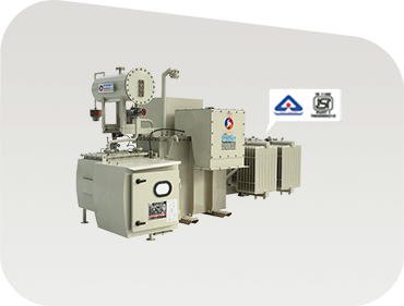
Oil-Immersed Foil Distribution Transformer
Engineered for utility distribution networks, industrial complexes, and commercial infrastructure. Built with hermetically sealed corrugated tanks or conservator systems with de-aerated mineral oil or synthetic ester fluids.
Primary Advantage: Superior impulse voltage withstand and maximum short-circuit endurance in harsh outdoor environments.
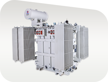
Renewable Inverter Duty Foil Transformer
Specifically designed to handle the multi-winding low-voltage inputs (up to 4 separate LV windings) from solar central inverters or wind turbine converters. Features reinforced foil insulation to withstand daily thermal cycling.
Primary Advantage: Mitigates inverter high-frequency switching harmonics and prevents DC bias core saturation.
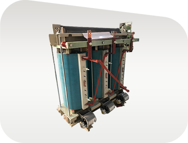
Cast Resin Dry-Type (CRDT) Foil Transformer
Vacuum-cast epoxy resin dry-type transformer with foil-wound LV and HV coils for indoor, explosion-proof, and environmentally sensitive applications such as hospitals, high-rises, airports, and underground metros.
Primary Advantage: Self-extinguishing, moisture-proof, and virtually maintenance-free operation in strict fire safety zones.
Need Custom Foil Transformer Engineering Specifications?
Our senior design team provides complete technical dossiers including GA drawings, loss calculations, vector group confirmation, and guaranteed technical particulars (GTP) tailored to your project requirements.
4. Future Procurement & Product Development Trends (2025–2035)
As global energy markets accelerate toward carbon neutrality and digital grid automation, the procurement landscape for distribution transformers is undergoing a massive transformation. Utilities in Europe, North America, the Middle East, and Asia-Pacific are moving away from evaluating transformers solely on initial purchase price, adopting Total Cost of Ownership (TCO) and Environmental, Social, and Governance (ESG) compliance metrics instead. Below are the key technological and procurement trends shaping the future of Foil Winding Distribution Transformers over the next decade.
4.1 Integration with Biodegradable Ester Dielectric Fluids
Traditional mineral transformer oil is increasingly being replaced by natural ester (vegetable-based) and synthetic ester fluids. Ester fluids possess fire flash points exceeding $300^{\circ}\text{C}$ (K-class designation) and are 99% biodegradable within 28 days. When paired with foil windings, ester liquids offer a synergistic benefit: because foil windings maintain lower hot-spot temperatures, the thermal oxidation rate of ester fluids is drastically reduced, allowing transformers to operate at higher emergency overload capacities without degrading the fluid or insulation paper.
4.2 Adoption of Ultra-Low Loss Energy Efficiency Mandates
Global regulatory bodies are enforcing stricter loss limits to minimize distribution network technical losses:
- India (BIS 1180): Mandatory compliance with Level 1 and Level 2 efficiency figures, with transition toward Level 3 super-efficient standards for public utility procurements.
- European Union (EcoDesign Directive Tier 2): Strict maximum allowable load and no-load losses ($P_k$ and $P_o$) for liquid-immersed and dry-type transformers.
- United States (DOE 2016 Efficiency Standards): High minimum efficiency levels across all single-phase and three-phase commercial distribution transformers.
Foil winding technology is critical to meeting these stringent eco-design standards. By maximizing core window space utilization and minimizing stray load losses, foil-wound designs allow engineers to utilize premium-grade Cold-Rolled Grain-Oriented (CRGO) silicon steel (such as Hi-B laser-scribed grades) and amorphous metal core alloys far more efficiently than wire-wound designs.
4.3 Smart Transformer Integration: Real-Time IoT Sensing & Asset Health Monitoring
The rise of Smart Grids demands intelligent distribution assets. Modern foil-wound transformers are increasingly specified with embedded Fiber-Optic Temperature Sensors directly woven into the inner foil layers during winding. Connected to IoT-enabled Online Dissolved Gas Analysis (DGA) modules, oil level monitors, and digital bush-monitoring systems, these smart units feed real-time health index metrics to utility SCADA systems. This transition enables predictive maintenance schedules, preventing unexpected grid outages and optimizing transformer loading during peak EV charging periods.
5. Why Leading Global Procurement Teams Choose Synergy Transformers
Selecting a manufacturing partner for critical power infrastructure requires verifiable technical competence, certified quality management systems, and transparent manufacturing traceability. Established in 2004 in Rajkot, Gujarat, India, Synergy Transformers Pvt. Ltd. has grown into a internationally recognized manufacturer of distribution transformers, power transformers, dry-type transformers, and specialized inverter duty units.