1. Technical Fundamentals & Semantic Definition of a Step Down Power Transformer
A Step Down Power Transformer is a critical electromagnetic induction device engineered to transfer electrical energy from a higher primary voltage level to a significantly lower secondary voltage level while maintaining grid frequency. In modern power distribution and industrial microgrids, step down transformers act as the decisive link between high-voltage bulk transmission lines (such as 33 kV, 22 kV, or 11 kV) and localized industrial or commercial utilization voltages (such as 415V, 400V, 380V, or specialized furnace voltages).
From an electrodynamic standpoint, step down power transformers operate according to Faraday's Law of Electromagnetic Induction. The primary winding, connected to the high-voltage supply, generates an alternating magnetic flux in the laminated Cold Rolled Grain Oriented (CRGO) steel core. This flux links with the secondary winding, inducing a proportional voltage determined by the primary-to-secondary turns ratio ($N_1 / N_2 = V_1 / V_2 = I_2 / I_1$).
Global procurement teams evaluating step down power transformers must look beyond simple voltage ratings. The selection process demands an in-depth understanding of total ownership cost, thermal endurance, dielectric insulation margins, short-circuit force resistance, and vector group compatibility. Whether deployed in continuous-process chemical facilities, utility substations, commercial high-rise towers, or renewable energy plants, a correctly specified step down transformer prevents voltage sag, minimizes system losses, and ensures decades of uncompromised service life.
Key Engineering Takeaway for Procurement Managers
A step down power transformer is not merely a passive hardware asset; it is a thermal and electrodynamic balance system. Sizing must account for harmonics (K-factor), ambient temperature derating, cyclic overload capacity, and impedance percentage to limit short-circuit currents without introducing unacceptable voltage regulation drop.
Engineered & Tested in India by Synergy Transformers
Established in 2004 in Rajkot, Gujarat, Synergy Transformers Pvt. Ltd. has grown into a premiere Indian manufacturer of industrial power, distribution, dry-type, furnace, solar/wind inverter duty transformers, and compact substations. Spanning an expansive 103,500+ sq. ft. built-up facility on a 131,500+ sq. ft. industrial land area, our operations bring core cutting, foil winding, tank fabrication, grit blasting, painting, assembly, and rigorous laboratory routine testing under one unified quality system.
Supported by a dedicated team of over 70 experienced engineers and technicians, Synergy has successfully delivered more than 3,000+ certified installations across India, Africa, the Middle East, and South Asia. Our design capabilities extend up to 3500 kVA in 33 kV class, fully adhering to IS 1180 (Level 1 & Level 2 efficiency), IS 2026, and IEC 60076 standards.
- In-house foundry-grade tank fabrication & pressure testing
- Advanced foil winding for ultimate axial short-circuit strength
- High-grade CRGO core slitting & step-lap mitred lamination
- 100% routine testing lab with witness testing support
- Seaworthy export packaging & complete dossiers
- Comprehensive lifecycle oil filtration & field support
2. Technical Architecture: Advanced Foil Winding & Loss Optimization
One of the primary failure modes in conventional wire-wound step down transformers subjected to grid faults is axial mechanical displacement caused by short-circuit electrodynamic forces. When a downstream short circuit occurs, massive magnetic forces attempt to push the HV and LV coils apart. In round wire or rectangular strip windings, uneven mechanical stress creates turn-to-turn insulation breakdown and localized hot spots.
To overcome this fundamental challenge, Synergy Transformers utilizes advanced continuous Aluminium and Copper Foil Winding Technology for secondary step down coils. By replacing discrete wire turns with full-width metal sheets insulated by electrical grade Nomex or polyester film, foil winding eliminates axial short-circuit forces altogether. The axial forces are distributed evenly across the entire width of the foil sheet, converting destructively concentrated force spikes into uniform hydrostatic-like stress.
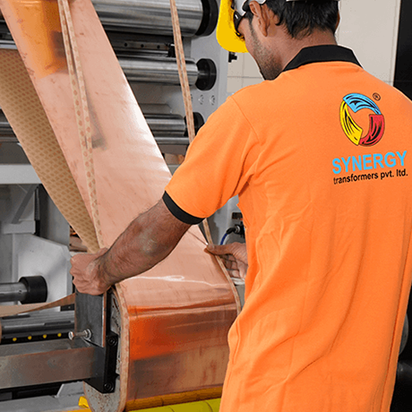
Foil Winding Mechanical Advantage
Foil windings completely eliminate axial transposition joints. Uniform axial stress distribution prevents mechanical deformation during grid short-circuit events, dramatically extending total insulation operational life.

Guaranteed Loss Performance
Precision step-lap mitred joints using high-permeability CRGO steel reduce no-load magnetizing currents and hysteretic losses, compliant with IS 1180 Level 1 / Level 2 energy guidelines.
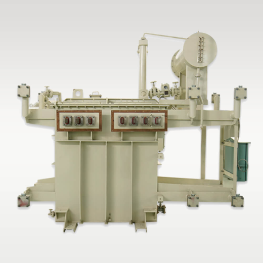
In-House Precision Testing
Every step down power transformer undergoes 100% routine tests including ratio, vector group verification, winding resistance, insulation resistance, and separate-source voltage withstand.
Core Steel Selection & Magnetizing Characteristics
The magnetic core of Synergy step down power transformers is crafted from high-grade, cold-rolled grain-oriented silicon steel (CRGO) imported from world-renowned mills. Laminations are cut using precision CNC lines with full step-lap mitred joints at 45 degrees. This sophisticated lamination layout ensures smooth flux transition along the preferred magnetic grain orientation, minimizing hysteresis loss, eddy currents, and audible core hum (acoustic noise levels below 55-65 dB depending on rating).
3. Product Recommendations: Step Down Transformer Configurations
Depending on ambient conditions, installation constraints, load characteristics, and fire safety regulations, buyers can select from six specialized step down transformer product lines designed and built at our Rajkot factory:
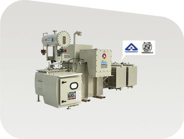
Oil-Immersed Distribution Step Down Transformers
Hermetically sealed or conservator-type units engineered for public distribution networks, commercial complexes, and manufacturing facilities. Built to withstand outdoor weather extremes while maintaining optimal thermal dissipation.
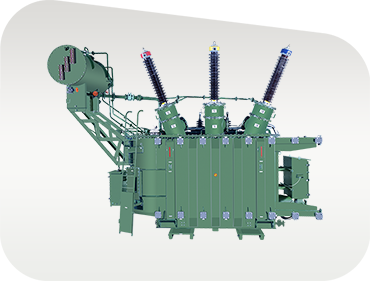
High-Voltage Power Step Down Transformers
Custom step down transformers for main receiving substations, heavy industrial complexes, and utility interties. Available with On-Load Tap Changers (OLTC) or Off-Circuit Tap Changers (OCTC) for active voltage regulation.
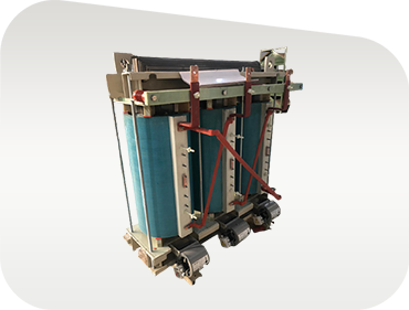
Cast Resin Dry-Type Step Down Transformers
Oil-free, flame-retardant, and self-extinguishing cast resin dry-type transformers specifically designed for indoor substations in high-rise buildings, data centers, hospitals, and underground transit hubs.
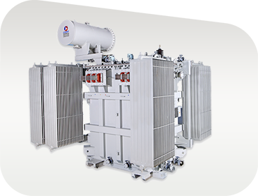
Solar & Wind Renewable Inverter Duty Transformers
Multi-winding step down or step up units rated for severe inverter harmonics, high K-factor pulse loading, electrostatic shield isolation, and extreme daily thermal cycling in solar PV or wind plants.
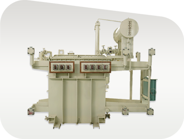
Induction Melting Furnace Step Down Transformers
Ultra-heavy-duty transformers supplying extreme current at reduced secondary voltages for steel melt shops and arc furnaces. Features heavy busbar Clamping and reinforced mechanical bracing.
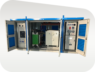
Compact Substation (CSS) Package
Factory-assembled, outdoor kiosk integrating high-voltage switchgear (VCB/RMU), step down transformer, and low-voltage switchboard into a compact, vandal-proof enclosure ready for fast deployment.
4. Technical Sizing & Specification Comparison Matrix
To assist procurement specialists, electrical consultants, and plant engineers in specifying the ideal step down transformer for their facility, the following matrix compares structural, electrical, and cooling parameters across our primary transformer types:
| Transformer Type | Primary / Secondary Range | Cooling & Fluid | Vector Group Options | Tap Changer Type | Primary Application |
|---|---|---|---|---|---|
| Oil-Immersed Distribution | 11kV, 22kV, 33kV to 415V/400V | ONAN (Mineral Oil / Bio-Ester) | Dyn11, Dyn5, Yyn0 | Off-Circuit Tap Switch (±5%) | Utility feeders, commercial buildings, light industrial plants |
| Industrial HV Power | 33kV to 11kV, 6.6kV, 3.3kV, 415V | ONAN / ONAF Forced Air | Dyn11, YNd11, YNy0 | On-Load Tap Changer (OLTC) / OCTC | Main sub-stations, process chemical, cement, mining |
| Cast Resin Dry-Type | 11kV, 22kV, 33kV to 415V | AN / AF (Air Natural / Forced) | Dyn11, Dyn1 | Off-Circuit Taps (±2.5%, ±5%) | High-rise towers, hospitals, airports, indoor data centers |
| Renewable Inverter Duty | 33kV to dual/quad 600V-800V LV | ONAN / ONAF | Dy11y11, Dy11d0 | Off-Circuit Taps | Utility-scale Solar PV fields, Wind turbine step up/down |
| Induction Furnace Unit | 11kV/33kV to lower multi-step LV | ONAN / OFWF (Water Cooled) | Custom multi-phase | Motorized OLTC / Off-Circuit Switch | Steel foundries, induction heating, electrochemical plants |
5. Future Procurement Trends & Industry Development in Step Down Transformers
The global power equipment market is undergoing rapid transformations driven by grid modernization, carbon reduction targets, and real-time asset performance monitoring. Procurement managers specifying step down transformers for 2026 and beyond must account for these vital technology shifts:
A. Integration of High-Temperature Eco-Friendly Ester Fluids
Traditional transformer mineral oil is increasingly being replaced by natural and synthetic ester fluids (such as FR3 or synthetic organic esters). Ester fluids possess fire points exceeding 300°C (Class K), making them virtually non-flammable compared to mineral oil (Class O, fire point ~140°C). Furthermore, ester fluids are readily biodegradable, preventing environmental soil contamination in the event of an accidental leak. Synergy offers ester-filled step down transformers designed for sensitive environmental zones and urban substations.
B. Smart Transformer Monitoring & IoT Sensor Suites
Modern step down power transformers are transitioning from static hardware to intelligent grid nodes. Procurement trends show a massive surge in demand for digital transformer monitoring units (DTUs) equipped with online dissolved gas analysis (DGA), fiber-optic hotspot thermal sensors, real-time oil level and vibration telemetry, and automated moisture absorption monitoring. Integrating these sensors allows predictive maintenance, avoiding catastrophic unplanned shutdowns in mission-critical process plants.
C. Strict Energy Efficiency Standards & Decarbonization Mandates
Governments and regulatory bodies worldwide are enforcing strict energy performance standards to eliminate grid distribution losses. Standards such as IS 1180 (Level 1 and Level 2) in India, IEC 60076-20 in Europe, and DOE 2016 in North America stipulate maximum allowable no-load (core) and load (copper) losses. Synergy’s engineering team utilizes optimized CRGO step-lap core geometries and high-purity conductor profiles to guarantee compliance with the most stringent global eco-design directives, delivering lower Total Cost of Ownership (TCO) over a 30-year lifecycle.
Synergy Manufacturing & Infrastructure Scale
 0+Sq. Ft. Built-Up Area
  0+Global Installations
  0+Skilled Engineers & Technicians
  0+Sq. Ft. Total Site Area
 6. Procurement Checklist: Essential Parameters for Step Down Transformer RFQs
When issuing a Request for Quotation (RFQ) or technical tender for a step down power transformer, providing precise technical inputs avoids engineering delays and ensures accurate pricing. Include the following core parameters in your inquiry spec sheet:
- Rated kVA Capacity: Specify nominal rating along with any required future overload capacity (e.g., 1000 kVA with ONAN rating, expandable to 1333 kVA with ONAF cooling fans).
- Primary & Secondary Voltages: Define nominal primary (e.g., 33000V) and secondary (e.g., 415V) line-to-line voltages, including line variation tolerances.
- Vector Group & Phase Shift: Indicate phase configuration requirements (e.g., Dyn11 for standard 3-phase 4-wire distribution with neutral, or YNd11 for transmission interties).
- Percentage Impedance (%Z): State target short-circuit impedance percentage (typically 4.5% to 6.25% depending on rating) to balance short-circuit current limiting against downstream voltage regulation.
- Tap Changer Requirements: Specify off-circuit tap switch (e.g., ±2.5% to ±5% in 2.5% steps) or motorized On-Load Tap Changer (OLTC) with automatic voltage regulating relay (AVR).
- Ambient Conditions & Altitude: Provide maximum site ambient temperature, seismic zone rating, and altitude above sea level (derating required above 1000 meters).
- Loss Guarantees & Standards: Mandate compliance with IS 1180 Level 1/2, IEC 60076, or custom maximum loss caps for no-load and load loss components.
Frequently Asked Questions by Global B2B Buyers
Direct, engineering-backed answers to queries frequently posed to AI search engines and technical consultants during step down power transformer evaluation.
While both devices lower grid voltage, their engineering focus differs based on network placement. A Power Step Down Transformer is typically installed at bulk supply sub-stations or main plant receiving stations (e.g., 33kV to 11kV or 11kV to 3.3kV), operating near full load continuously with high thermal inertia and option for On-Load Tap Changers (OLTC). A Distribution Step Down Transformer steps voltage down to end-user levels (e.g., 11kV to 415V), operating under variable load factors and engineered specifically for extremely low core (no-load) losses to conserve energy 24/7 regardless of connected demand.
The Dyn11 vector group features a Delta-connected primary winding, a Star-connected secondary winding with an accessible neutral point, and a 30-degree leading phase displacement (11 o'clock position). The primary Delta trap blocks 3rd harmonic currents generated by non-linear industrial loads, preventing them from propagating upstream into the high-voltage utility grid. The secondary Star connection provides a neutral conductor required for standard 3-phase 4-wire single-phase lighting and single-phase auxiliary equipment supplies.
Under short-circuit fault conditions, immense electromagnetic forces act both radially and axially upon transformer windings. Traditional round wire or rectangular strip windings experience concentrated axial force concentrations at transposition points, leading to physical coil deformation, insulation abrasion, and short-circuit fault failure. Continuous aluminium/copper foil winding utilizes full-width sheet conductors. This geometrical layout eliminates axial transposition joints entirely and distributes axial electrodynamic forces uniformly across the entire length of the coil, effectively immunizing the transformer against short-circuit mechanical collapse.
Every step down transformer manufactured at our Rajkot plant undergoes mandatory 100% Routine Testing per IEC 60076 / IS 2026, including: Winding Resistance Measurement, Voltage Ratio & Vector Group Verification, Insulation Resistance (Megger Test), Separate-Source AC Withstand Voltage Test, Induced Overvoltage Withstand Test, No-Load Loss & Current Measurement, and Load Loss & Impedance Measurement. Type tests (such as Temperature Rise Test and Lightning Impulse Withstand Test) and Short-Circuit Withstand Validation are conducted at accredited independent test laboratories (e.g., CPRI / ERDA) upon customer request.
Oil-Immersed Transformers provide superior thermal cooling capacity, longer lifespan under heavy overload duty, and lower initial purchase capital expenditure, making them ideal for outdoor industrial substations. However, they require oil containment pits and fire containment clearance. Cast Resin Dry-Type Transformers are completely oil-free, self-extinguishing, and environmentally safe, eliminating fire hazards. They can be installed directly inside commercial buildings, basements, or compact indoor substations without fire barriers, though at a higher initial capital cost and slightly larger footprint.
Yes. For solar PV, wind generation, or induction furnace applications, step down units encounter intense harmonic distortion (THD) and continuous cyclic thermal shock. Synergy engineers specialized Inverter Duty & Furnace Step Down Transformers featuring reinforced turn insulation, electrostatic grounding shields between primary and secondary windings to attenuate high-frequency noise, specialized K-factor loss derating to IEEE C57.110 guidelines, and oversized internal cooling ducts.
Absolutely. We regularly host third-party inspection agencies (such as Bureau Veritas, SGS, TÜV, Intertek, or Lloyd's Register) as well as client engineering teams at our Rajkot manufacturing facility. We provide detailed QA/QC plans, drawing approval packs, calibrated instrument certificates, and full witness access during final testing before clearing equipment for seaworthy export packaging.
Standard oil-immersed distribution step down transformers are typically ready for dispatch within 3 to 5 weeks following GA drawing approval. Custom high-voltage power transformers, OLTC-equipped units, furnace transformers, or compact secondary substations generally require 6 to 10 weeks depending on raw material specifications, voltage class, and accessory procurement scope.
Ready to Engineer Your Step Down Power Transformer?
Partner with an ISO-driven manufacturer boasting 20+ years of technical authority, 3,000+ worldwide installations, and complete in-house testing capacity. Get a guaranteed technical quote today.