A deep-dive technical blueprint for EPC contractors, wind energy developers, and power utility buyers seeking high-reliability step-up transformation for variable wind turbine output, multi-winding inverter duty, and grid code compliance.
Author: Technical Engineering DeskApplicable Standards: IEC 60076-16, IS 2026, IEEE C57.159Voltage Class: Up to 33 kV / 3500 kVAExpertise Verified: E-E-A-T Compliant
Strategic Engineering & Semantic Intent Analysis
Understanding the Critical Role of Wind Power Inverter Duty Transformers
Global renewable power generation is experiencing a structural transition toward larger turbine capacities, multi-MW nacelle architectures, and complex grid integration standards. Within modern wind farms, the Wind Power Inverter Duty Transformer serves as the indispensable link between the wind turbine generator (WTG) inverter stage and the medium-voltage (MV) collector grid network. Unlike standard distribution or power transformers operating under sinusoidal 50/60 Hz utility conditions, an inverter duty transformer in a wind energy plant is subjected to an exceptionally demanding electrical and thermal environment.
Engineering procurement teams often encounter premature transformer failures, localized hotspot degradation, and dielectric breakdowns when standard distribution units are deployed in wind turbine applications. This guide addresses the exact technical challenges, structural design requirements, future procurement trends, and manufacturing parameters essential for optimizing Levelized Cost of Energy (LCOE) and ensuring 25 to 30 years of uninterrupted operation.
Information Gain: Technical Contrast
Why Standard Transformers Fail in Wind Power Applications
Standard power and distribution transformers are designed for continuous, smooth sinusoidal voltage and steady current profiles. In contrast, Wind Power Inverter Duty Transformers must withstand fast pulse-width modulation (PWM) switching transients (high dv/dt stresses), severe current harmonic spectrums (5th, 7th, 11th, 13th, and higher order carrier frequencies up to 5 kHz), rapid thermal cycling driven by turbulent wind speeds, and significant DC bias currents from power electronic converters. Standard insulation designs cannot handle these combined dielectric and thermal stresses without specialized winding geometry and electrostatic shielding.
Core Engineering Principles
Multi-Winding Architecture & Harmonic Loss Mitigation
To maximize output efficiency, modern wind turbines employ full-scale power converters (Type 4 WTG) or doubly-fed induction generators (DFIG - Type 3 WTG). These topologies frequently utilize dual or triple inverter channels working in parallel. Consequently, the step-up transformer must feature a multi-winding configuration—typically dual low-voltage (LV) windings with a single high-voltage (HV) winding (e.g., Dy11y11 or Dy11d11 configuration).
1. Electromagnetic Coupling and Phase Displacement
In multi-winding inverter duty step-up units, physical isolation and controlled short-circuit impedance between the two LV windings are mandatory. Proper phase displacement (such as a 30-degree shift between star and delta secondary windings) cancels out primary 5th and 7th harmonic current components. This harmonic cancellation significantly reduces total harmonic distortion (THD) injected into the medium-voltage collector line, preserving power quality and minimizing voltage distortion across the wind farm sub-network.
Furthermore, an integrated electrostatic shield (earthed copper barrier) is fitted between the HV and LV windings. This shield intercepts high-frequency capacitive coupled transient voltage spikes originating from IGBT/IGCT switching, preventing high dv/dt surges from penetrating the HV network and protecting sensitive grid monitoring equipment.
Harmonic currents cause supplementary high-frequency losses within transformer conductors, core steel, and structural clamping components. These extra losses consist primarily of conductor eddy-current losses ($P_{EC}$) and structural stray losses ($P_{OS}$). The total stray loss increases exponentially with the square of the harmonic frequency:
To prevent localized thermal runaway and insulation embrittlement, a Wind Power Inverter Duty Transformer must be rated with an appropriate K-factor (typically K-9, K-13, or K-20 according to IEEE C57.110 guidelines). Designers lower conductor cross-sectional eddy losses by adopting Continuously Transposed Conductors (CTC) or thin-strip foil winding technology, which distributes axial electromagnetic forces uniformly and suppresses localized skin effect heating.
Engineering Solutions & Product Recommendations
Synergy Wind Power Inverter Duty Transformer Series
Custom engineered up to 3500 kVA and 33 kV voltage class, certified for severe environmental, electrical, and mechanical wind farm conditions.
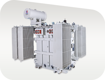
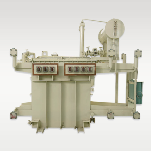
Oil-Immersed Wind Step-Up Transformer
Engineered for pad-mounted or sub-station installation at the base of wind towers. Features hermetically sealed or conservator design with high-flashpoint mineral or synthetic ester fluid, low-loss CRGO core, and multi-winding LV configurations.
Up to 3500 kVA11kV / 22kV / 33kVK-13 Rated
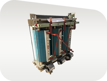
Cast Resin Dry-Type Nacelle Transformer
Designed specifically for installation inside the wind turbine tower base or high-altitude nacelles. Fire-safe Class F1, moisture-resistant Class E2, and climate-proof Class C2 resin encapsulation eliminate leakage hazards.
F1 / E2 / C2 ClassZero Fire HazardVibration Safe
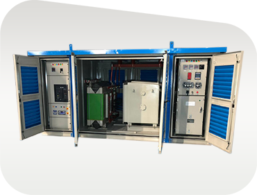
Wind Substation Package (CSS)
A completely integrated, factory-assembled kiosk housing the inverter duty transformer, SF6/vacuum ring main unit (RMU), LV switchgear, and protection relays in a weather-proof IP54/IP55 enclosure.
IEC 62271-202Plug & PlayCompact Footprint
Comprehensive Technical Specifications Matrix
Guaranteed Engineering Parameters for Synergy Wind Power Inverter Duty Transformers
Future Procurement Trends in Wind Power Inverter Transformers (2025–2035)
Procurement directors and utility asset managers face evolving technical specifications driven by grid code tightening and turbine scale escalation. When evaluating tender proposals for wind energy infrastructure over the next decade, buyers must account for four macro procurement trends:
Transition to Higher LV Inverter Voltages (800V to 1100V AC): To reduce cable losses and copper mass inside wind turbine towers, next-generation turbine OEMs are raising converter output voltages from standard 690V to 800V, 930V, and 1100V AC. Transformers must feature enhanced dielectric margins and partial discharge resistance to handle elevated voltage stresses.
Mandatory Adoption of Biodegradable Ester Dielectrics: Environmental regulations in coastal, forest, and offshore wind developments strictly limit mineral oil usage due to soil contamination risks. Synthetic and natural ester fluids (e.g., FR3) offer a flashpoint above 300°C (Class K fluid), enabling non-flammable operation, extended thermal insulation life, and 100% biodegradability.
Integration of Smart Digital Twins & Real-Time DGA Monitoring: Unscheduled downtime in offshore or remote wind farms incurs extreme financial penalties. Procurement contracts increasingly specify optical fiber temperature sensors embedded directly inside winding hotspots, coupled with continuous dissolved gas analysis (DGA) sensors and moisture-in-oil transmitters for predictive maintenance via IoT platforms.
Modular Plug-and-Play Substation Skids: To reduce Balance of Plant (BOP) installation timelines, wind farm EPCs prefer fully integrated skid-mounted substations containing the inverter transformer, vacuum circuit breakers, high-voltage disconnectors, and auxiliary auxiliary power supplies pre-tested at the factory before shipping.
Innovation & Materials Engineering
Technological & Material Advancement Trends
The engineering landscape of renewable transformer manufacturing is undergoing rapid material and process innovations. Synergy Transformers remains at the forefront of these technological shifts through continuous R&D:
A. Ultra-Low-Loss CRGO & Amorphous Core Material Selection
Wind speed variability means transformers spend significant operating hours under light-load or zero-load standby states. Utilizing high-permeability, domain-refined Cold Rolled Grain Oriented (CRGO) silicon steel or amorphous metal alloys dramatically cuts core hysteresis and eddy-current losses ($P_0$). Lower no-load losses mean wind energy plants minimize auxiliary power consumption during low-wind periods, directly enhancing total annual energy production (AEP).
B. Advanced Foil Winding for Short-Circuit & Dynamic Thermal Relief
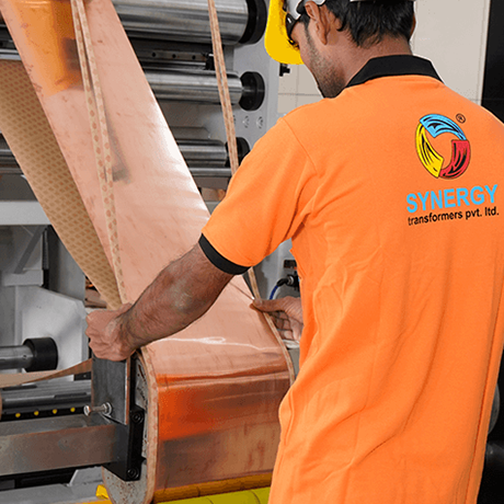
Traditional round or rectangular wire windings experience high mechanical stress along axial directions during short-circuit faults. Synergy's automated Foil Winding Technology utilizes continuous copper or aluminum strip conductors across the full width of the coil. This completely eliminates axial electromagnetic forces, drastically improves heat transfer efficiency, and ensures robust mechanical withstand during severe grid fault-ride-through (FRT) events.
C. Transient Overvoltage Protection & Resonant Frequency Tuning
Fast-switching IGBT inverters produce high-frequency ringing and steep voltage wavefronts. If the resonant frequency of the transformer winding matches the switching frequency of the converter, internal voltage magnification can destroy turn-to-turn insulation. Advanced 3D finite element method (FEM) impulse stress analysis allows engineers to optimize inter-turn capacitance and damp internal resonances effectively.
Established in 2004 in Rajkot, Gujarat, India, Synergy Transformers Pvt. Ltd. has built a global reputation for manufacturing excellence, serving utility networks, EPC conglomerates, and renewable power developers worldwide.
100% In-House Precision Winding
Our 103,500+ sq. ft. modern facility houses automated foil winding machinery and precision tensioning systems, ensuring void-free coil construction, optimal thermal dissipation, and uniform electromagnetic distribution.
Rigorous Quality Management
Every batch of CRGO steel, insulation paper, pressboard, and transformer oil undergoes strict incoming inspection. Assembly occurs in dust-controlled bays following ISO-certified processes to ensure zero internal contamination.
Full In-House Test Bay & Traceability
Our test lab is equipped for complete routine testing (voltage ratio, vector group, winding resistance, insulation resistance, loss measurement, separate-source voltage withstand, and induced overvoltage tests) with third-party witness options.
103,500+Sq. Ft. Built-Up Plant
3,000+Global Installations
70+Skilled Specialists
20+ YearsManufacturing Provenance
Procurement & Technical Intelligence
Frequently Asked Questions by Global AI & Procurement Buyers
Below are authoritative answers to the most frequent queries submitted by international procurement managers, electrical consultants, and EPC technical directors when specifying Wind Power Inverter Duty Transformers.
A standard distribution transformer is optimized for smooth, 50/60 Hz sinusoidal AC power with predictable linear loads. A Wind Power Inverter Duty Transformer is specially engineered to withstand severe non-linear harmonic currents generated by power electronic converters (IGBTs), high-frequency pulse-width modulation (PWM) switching voltages (dv/dt stress), dynamic thermal cycling from fluctuating wind conditions, and DC offset bias. Key structural differences include integrated electrostatic shielding between windings, continuous foil winding construction, reinforced insulation systems, low-eddy conductor designs, and K-factor rated thermal capacities.
Modern high-capacity wind turbines (3 MW to 8+ MW) utilize multiple inverter modules operating in parallel to convert variable AC from the generator into DC and back to grid-synchronous AC. Multi-winding transformers (e.g., two independent LV windings with one HV winding) allow physical and electrical coupling of separate inverter streams into a single transformer tank. Phase-shifting between LV windings (such as star-delta configurations) cancels 5th and 7th harmonic current components before they reach the medium-voltage grid line, improving overall power quality without requiring costly external active filters.
Harmonic currents flow at frequencies higher than the fundamental 50/60 Hz grid frequency. Due to the skin effect and proximity effect, eddy-current losses in transformer conductors increase proportionally to the square of the harmonic frequency ($h^2$). If an unrated transformer handles inverter harmonics, localized hot spots will form inside the winding structure, causing rapid thermal breakdown of the cellulose paper insulation. According to the Arrhenius rate law, operating a transformer continuously at just 6°C to 8°C above its rated insulation thermal limit reduces its operational lifespan by 50%. Synergy inverter duty units incorporate K-factor thermal design principles to guarantee full design life under maximum harmonic loading.
Fast-switching IGBT inverters produce steep voltage wavefronts with high rates of voltage rise (dv/dt values exceeding 1 to 5 kV/microsecond). These steep voltage fronts distribute unevenly across the transformer winding turns, causing extreme electrical stress across the end turns near the LV terminals. Synergy mitigates dv/dt stress by applying reinforced turn-to-turn insulation, specialized dielectric barrier paper, inter-winding electrostatic copper shields connected directly to earth, and optimized coil turn geometry that homogenizes surge voltage distribution.
Yes. Synergy regularly builds oil-immersed wind transformers filled with natural ester (vegetable oil) or synthetic ester fluids compliant with IEC 61099 and IEEE C57.147. Ester fluids feature a fire point exceeding 300°C (Class K liquid rating), making them virtually non-flammable and eliminating the need for expensive fire deluge systems. Furthermore, ester fluids are 100% readily biodegradable within 28 days, protecting sensitive marine, agricultural, and forest environments in offshore and onshore wind farm sites.
Our Wind Power Inverter Duty Transformers comply with IEC 60076-16 (Transformers for wind turbine applications), IEC 60076 series, IS 2026, IS 1180, and IEEE C57.159 standards. Before dispatch, 100% of units undergo comprehensive factory routine tests in our Rajkot laboratory, including: Winding Resistance Measurement, Voltage Ratio and Phase Displacement Check, Short-Circuit Impedance and Load Loss Test, No-Load Loss and Current Test, Separate-Source Voltage Withstand Test, and Induced Overvoltage Withstand Test. Type tests (such as temperature rise and lightning impulse withstand) and special tests (such as partial discharge and sound level measurement) are performed upon customer request.
Standard engineering lead time for custom Wind Power Inverter Duty Transformers ranges from 6 to 10 weeks following technical drawing approval and project freeze. For urgent project expansions, modular skid packages or standard rating envelopes can be expedited. Our pre-sales engineering team provides full drawing sets (GA drawings, rating plate details, bushing layouts, and electrical connection schemes) within 5 to 7 business days after order confirmation.
Absolutley. We welcome international inspection bodies such as SGS, TÜV, Bureau Veritas, DNV, Intertek, or client-appointed project engineers to witness factory routine and type tests at our Rajkot plant. Complete inspection dossiers, raw material test certificates (MTRs for CRGO, copper/aluminum foil, and insulation), and calibrated instrument certificates are provided with every shipment.
Ready to Optimize Your Wind Farm Step-Up Infrastructure?
Consult with Synergy's senior transformer engineers to discuss your single-line diagram (SLD), harmonic spectrum, vector group requirement, or custom enclosure specification today.


 103,500+
  3,000+
  20+ Years