☉ Manufacturing since 2004 · Rajkot, Gujarat, India ✉ [email protected] ☎ +91 958 627 7766
Technical Buyer Guide & Engineering Standards

Step Up Power Transformer Engineering & Procurement Guide: Technical Specifications, Selection Metrics, and Global Industry Trends

An authoritative guide for utility engineers, EPC contractors, renewable plant managers, and procurement officers evaluating high-reliability Step Up Power Transformers up to 3500 kVA and 33 kV class. Designed and manufactured by Synergy Transformers Pvt. Ltd.

Inquire Now Explore Product Range
Semantic Context & Grid Role

Understanding the Critical Role of Step Up Power Transformers in Electrical Grids

Why step-up transformation requires specialized thermal, mechanical, and dielectric engineering compared to standard step-down units.

In modern power systems, generation assets—ranging from utility-scale solar photovoltaic (PV) central inverters, wind turbine generators, thermal plant alternators, and industrial co-generation units—produce electricity at lower voltage levels, typically between 415 V, 690 V, 3.3 kV, 6.6 kV, or 11 kV. Transmitting large blocks of power across distribution or transmission grids at these low voltages is commercially impossible due to catastrophic I²R line losses and excessive cable copper cross-sections.

A Step Up Power Transformer serves as the fundamental bridge between power generation and energy transmission. By stepping up the generated voltage to higher system voltages (such as 11 kV, 22 kV, or 33 kV), the continuous line current drops proportionally for a given megawatt payload. This drastic reduction in current minimizes resistive losses, stabilizes system voltage regulation, and allows power utilities and independent power producers (IPPs) to transmit green power over vast geographic distances efficiently.

However, engineering a step-up transformer involves distinct technical challenges that step-down distribution transformers rarely face. Because step-up transformers are connected directly to dynamic generating sources—such as high-frequency PWM inverters or cycling industrial generators—their Low Voltage (LV) windings endure extremely high continuous currents, thermal cycling, dV/dt voltage transients, and severe electromagnetic stresses during external grid short-circuits. At Synergy Transformers Pvt. Ltd., our design team engineers each unit from the ground up to overcome these precise operational stresses.
Inquire Now
20+Years Industry Leadership
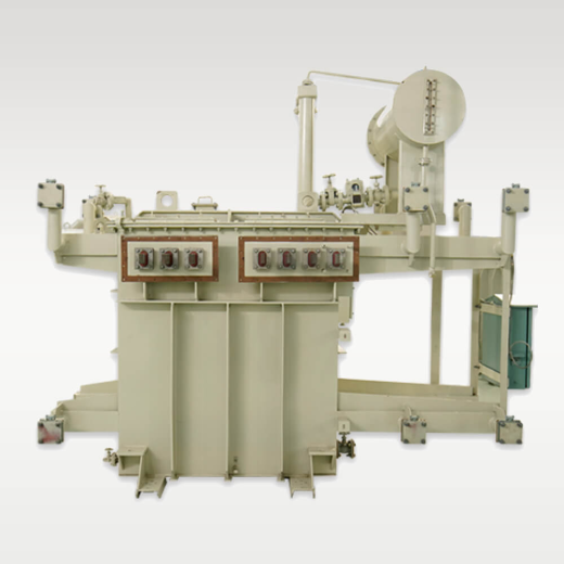
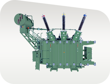
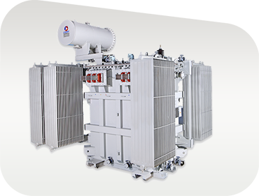
Step Up Power Transformer manufactured by Synergy Transformers
Product Selection & Specifications

Recommended Step Up Power Transformer Configurations

Explore tailored step-up transformer solutions optimized for specific generation technologies, environmental ambient conditions, and duty cycles.

Solar and Wind Inverter Duty Step Up Transformer

Solar PV Inverter Duty Step-Up Transformer

Engineered for multi-inverter solar blocks. Features split LV windings (Dy11y11 or Dyn11y11) to isolate central inverters, electrostatic shielding to attenuate dV/dt transients, and K-factor rated insulation to handle harmonic currents without over-heating.

250 – 3500 kVADual/Multi LVK-13 / K-20 Rated
Generator Step Up (GSU) Power Transformer

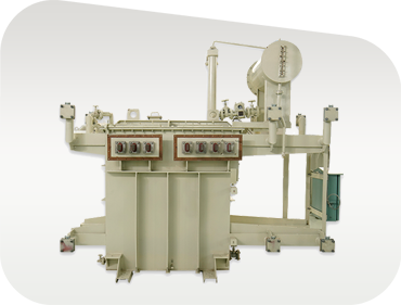
Generator Step Up (GSU) Power Transformer

Built for continuous, heavy-duty utility and industrial captive generation tie-ins up to 33 kV. Features custom On-Load Tap Changers (OLTC) or Off-Circuit Tap Changers (OCTC), ONAN/ONAF cooling, and ultra-low no-load loss CRGO cores.

Up to 3500 kVA11/22/33 kVOLTC / OCTC
Cast Resin Dry Type Step Up Transformer

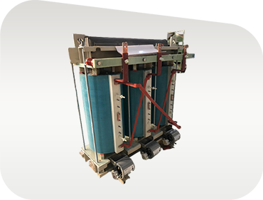
Cast Resin Dry-Type Step Up Transformer

Ideal for indoor substations, offshore platforms, wind turbine nacelles, and commercial high-rises requiring zero fire hazard. Moisture-proof, self-extinguishing Class F/H insulation complying with IEC 60076-11 (F1, E2, C2 environmental classes).

100 – 2500 kVAF1 / E2 / C2AN / AF Cooling
Oil Immersed Step Up Distribution Transformer

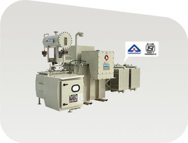
Hermetically Sealed Step Up Transformer

Maintenance-free hermetically sealed oil-immersed design for harsh outdoor environments. Prevents atmospheric oxidation and moisture ingress, preserving dielectric oil strength and extending maintenance intervals.

16 – 3150 kVAHermetically SealedIS 1180 / IEC 60076
Compact Secondary Substation with Step Up Transformer

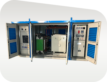
Compact Substation (CSS) Step-Up Package

Factory-assembled, turnkey step-up package integrating MV switchgear (RMU/VCB), step-up transformer, and LV protection panel inside an IP-rated weather-proof housing. Minimizes site civil works and speeds up project commissioning.

Turnkey KioskSF6 / VCB SwitchgearPlug & Play
Specialized High-Current Step Up Transformer

Heavy Industrial & Furnace Step-Up Transformer

Custom-engineered for industrial plants experiencing heavy cyclic shock loads, frequent short-circuits, and severe harmonic distortion. Reinforced mechanical clamping and active oil-directed cooling options available.

High-Current LVReinforced CoreHeavy Duty
Enterprise Advantage

Why Global Procurement Teams Choose Synergy Transformers

Established in 2004 in Rajkot, Gujarat, India, Synergy Transformers Pvt. Ltd. has grown into a premier global manufacturer of power, distribution, dry-type, furnace, and inverter duty transformers. Our integrated manufacturing eco-system allows complete quality control over every stage of transformer production.

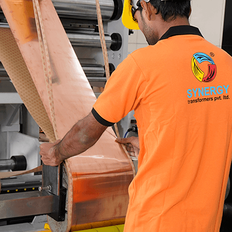
Spanning over 103,500+ sq. ft. of built-up facility on a 131,500+ sq. ft. industrial campus, our plant houses state-of-the-art core-cutting lines, automated foil and wire winding machines, vacuum drying ovens, in-house tank fabrication with shot-blasting and anti-corrosion painting booths, and advanced oil filtration units.

Our team of 70+ skilled electrical engineers and certified technicians ensures every step-up power transformer meets stringent international standards, including IS 1180, IS 2026, IEC 60076, and IEC 60076-11.

  • In-house foundry-grade tank fabrication & multi-layer poly-urethane painting
  • Automated foil winding technology ensuring uniform axial short-circuit withstand
  • High-grade CRGO core sourced exclusively from audited prime global mills
  • Full routine testing laboratory with support for witness and third-party inspection (SGS, BV, TÜV)
  • Export-ready seaworthy vacuum packaging with comprehensive dossier supply
  • Over 3,000+ successful installations across utilities, renewables, and heavy industries
Inquire Now Explore Our Infrastructure
3,000+Global Installations
Manufacturing Capacity

Auditable Infrastructure & Engineering Scale

Built-up manufacturing area icon 0+Sq. Ft. Built-Up Area
Satisfied clients icon 0+Global Installations
Engineering workforce icon 0+Engineers & Technicians
Total land area icon 0+Sq. Ft. Total Land Area
Technical Reference

Step Up Transformer Manufacturing Matrix & Tolerances

Review indicative manufacturing limits for procurement engineering teams and consulting engineers.

Technical parameters represent standard manufacturing envelopes. Custom ratings, impedance ranges, vector groups, and tap ranges are engineered to exact client specifications.
ParameterOil-Immersed Step Up TransformerCast Resin Dry-Type Step Up Transformer
Power Rating Range16 kVA to 3500 kVA100 kVA to 2500 kVA
Voltage Class RangeUp to 33 kV class (Primary/Secondary)Up to 33 kV class
Cooling MethodONAN / ONAF / KNAN (Ester oil)AN / AF (Air Natural / Air Forced)
Winding MaterialElectrolytic Copper / Aluminum (Foil or Wire)Electrolytic Copper / Aluminum Foil
Vector Group OptionsDyn11, Dyn1, YNd11, Dyn11y11 (Dual LV)Dyn11, Dyn1, YNd11
Insulation Thermal ClassClass A (105°C) / Class A+ (Ester)Class F (155°C) / Class H (180°C)
Tap Changer TypeOff-Circuit Tap Switch (OCTC) / On-Load Tap Changer (OLTC)Off-Circuit Tap Links (±2.5%, ±5%)
Applicable StandardsIEC 60076, IS 2026, IS 1180 Level 1 & 2IEC 60076-11, IS 11171, F1 / E2 / C2
Environmental RatingOutdoor C4/C5 Marine Grade PaintingIndoor IP20/IP23 Enclosure or Outdoor IP54
Buyer & Consultant FAQ

Frequently Asked Questions on Step Up Power Transformer Procurement

Direct, intent-based technical answers for global buyers, electrical consultants, and EPC contractors.

A Step Up Power Transformer is specifically designed to accept generation or inverter output voltage at its Low Voltage (LV) winding (e.g., 415V, 600V, 690V, or 11kV) and step it up to a higher High Voltage (HV) transmission level (e.g., 11kV, 22kV, or 33kV). Technically, the LV winding experiences significantly higher continuous current and dynamic electromagnetic forces during grid disturbances. Consequently, step-up transformers demand reinforced mechanical clamping, specialized foil or heavy-section winding geometry, enhanced dV/dt dielectric insulation to handle high-frequency voltage transients, and optimized cooling design for continuous high-load duty cycles.

Foil winding uses continuous electrical-grade copper or aluminum sheet across the full axial height of the coil, replacing multi-turn insulated wire. This completely eliminates transposition joints and creates an electrically balanced layer structure. As a result, axial short-circuit forces during external grid faults are virtually neutralized. Additionally, foil winding provides superior heat transfer with lower hot-spot thermal gradients, eliminates internal air voids, and substantially extends the operational lifespan under heavy cyclic load conditions.

For solar PV power plants, multi-inverter step-up transformers frequently employ dual LV or triple LV winding structures (such as Dy11y11 or Dyn11y11) connected to separate solar central inverters. This design decouples the inverters, minimizes circulating harmonic currents, and optimizes overall inverter efficiency. The vector phase shift between secondary windings can also assist in harmonic cancellation on the primary HV side.

Inverter-fed renewable step-up transformers operate under non-sinusoidal voltage and current profiles rich in high-frequency harmonics. Synergy mitigates harmonic heating by oversizing the conductor cross-section, implementing electrostatic shielding between primary and secondary windings, utilizing low-loss high-permeability CRGO steel cores (reducing stray flux losses), and specifying Class H or high-temperature insulation systems rated for K-4, K-13, or K-20 duty cycles.

Synergy Transformers engineers and tests Step Up Power Transformers in compliance with IEC 60076, IS 2026, IS 1180, and IEEE C57 standards. Every manufactured transformer undergoes 100% routine testing in our state-of-the-art testing bay (including winding resistance, voltage ratio, vector group verification, insulation resistance, separate-source AC withstand voltage, induced overvoltage, no-load loss, and load loss measurement). Customers and international third-party inspection agencies (such as Bureau Veritas, SGS, TÜV, or Lloyd's Register) are welcomed to conduct full witness testing prior to seaworthy packaging and dispatch.

Standard distribution-class step-up units (up to 2500 kVA) typically require 3 to 5 weeks from drawing approval to factory acceptance testing. Specialized multi-winding solar/wind inverter transformers or heavy power units (up to 3500 kVA / 33 kV) require approximately 6 to 9 weeks. Customization parameters include voltage ratings, dual LV inputs, OLTC vs. Off-Circuit Tap Changers, mineral oil vs. natural ester bio-fluids, specialized paint coatings (C4/C5 marine grade), and custom physical dimensions for compact substation integration.

Direct Factory Engagement

Request a Step Up Power Transformer Quote

Factory desk operating hours: Monday to Saturday, 09:00 – 18:00 IST. Overseas export tenders receive priority pre-sales engineering assistance.

Manufacturing Facility

National Highway No. 27, near Pipaliya Toll Plaza, Village Sadak Pipaliya, Tal. Gondal, Dist. Rajkot – 360311, Gujarat, India

Registered Office

"Diksha Parva", Shree Society Street No. 4, Opp. Tagore Vidhyalay, Nana Mava Road, Rajkot – 360005, Gujarat, India

Inquire Now
Proven Reliability

Trusted By Utilities, EPCs & Industrial Leaders

Power utilities, renewable project developers, and heavy industrial groups specifying Synergy step-up transformers worldwide.

Client logo 1
Client logo 2
Client logo 3
Client logo 4
Client logo 5
Client logo 6
Client logo 7
Client logo 8
Client logo 9
Client logo 10
Client logo 11
Client logo 12
Client logo 13
Client logo 14