Choosing the 2026 best Foil Winding Distribution Transformer requires more than comparing catalog ratings. Real installations reveal the difference.
John J. Winders Jr., a respected transformer engineering author, describes a transformer as “a static device that transfers electrical energy from one circuit to another.” This simple definition still guides practical selection. A strong foil-wound design should deliver stable voltage, controlled temperature rise, low partial discharge, and dependable short-circuit strength. Its copper or aluminum foil conductors should also reduce axial stress during fault conditions.
The best choice depends on the site. A hospital needs quiet operation and strong reliability. A factory may prioritize harmonic performance, overload tolerance, and easy maintenance. Outdoor substations require suitable enclosures, corrosion protection, and verified insulation coordination. Check the data.
Field experience matters here. Technicians often inspect winding tightness, cooling paths, joints, and noise levels before commissioning. A transformer can look excellent on paper yet perform poorly when ventilation is restricted. That happens.
In 2026, buyers should review temperature-rise tests, impulse-test results, efficiency data, acoustic measurements, and routine quality records. Manufacturer experience with similar loads is equally valuable. Certification helps, but it does not replace engineering judgment.
There is no universal winner.
A reliable Foil Winding Distribution Transformer should match the network’s voltage, load profile, environment, and future expansion plans. Independent inspection can strengthen confidence, especially for critical facilities. Still, specifications are not infallible. Site conditions change, and forecasts can be wrong. The most responsible selection combines verified evidence, practical expertise, and a willingness to question attractive claims.
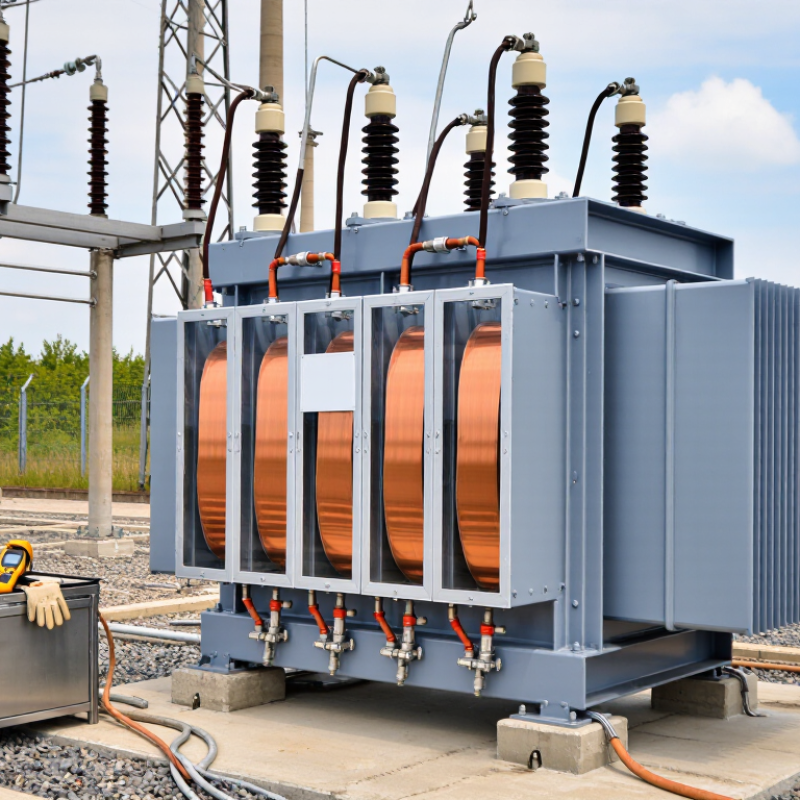
What Is the 2026 Best Foil Winding Distribution Transformer?
For low-voltage windings, foil conductors spread current across a wide, thin metal strip. This geometry reduces radial electric stress and limits circulating-current losses when designed correctly. Copper foil offers higher conductivity in a smaller cross-section. Aluminum foil weighs less and usually costs less. Its larger required section changes the winding dimensions. Neither material wins every project.
During field commissioning, I look beyond the nameplate. I check load profile, ambient temperature, ventilation, impedance, and short-circuit duty. A 400 V system feeding welders or data equipment can produce severe current pulses. Foil helps manage them through broad contact surfaces and even current distribution. Layer insulation must remain uniform. A wrinkle can create a hot spot. Small details matter.
Copper usually provides compact windings and strong mechanical performance, but its price and weight can challenge installation. Aluminum needs careful joints and larger terminals because oxide films and higher resistivity affect connections. Good designs use controlled compression, rounded foil edges, and temperature sensors near the hottest region. Manufacturers should verify temperature rise, impulse withstand, losses, and short-circuit strength through documented testing. I would not call one foil material best without those results. Even a clean calculation can miss airflow restrictions in a crowded room. Site measurements may change the decision.
Copper offers higher electrical conductivity, which can reduce conductor cross-sectional requirements and resistive losses in low-voltage, high-current foil windings. Aluminum is significantly lighter and can provide a practical weight advantage, but equivalent electrical resistance generally requires a larger foil cross-section. Final transformer selection also depends on thermal limits, available space, mechanical strength, connections, and total cost.
The 2026 best foil winding distribution transformer should be judged against construction standards, not marketing claims. IEC 60076-11 defines requirements for dry-type transformers used indoors and outdoors. It addresses environmental, climatic, and fire behavior classes. These details matter in a dusty plant or a humid utility room.
A foil winding can create a compact low-voltage winding with controlled current distribution. However, foil alone does not prove reliable construction. Designers must manage insulation spacing, thermal expansion, resin curing, and mechanical forces during short circuits. IEC 60076-11 includes performance tests for temperature rise, dielectric strength, partial discharge, and environmental behavior. Each test should match the declared application.
IEEE C57.12.01 provides general requirements for dry-type distribution and power transformers. It covers ratings, insulation systems, terminals, construction, and routine or design testing. Engineers often compare nameplate data with actual load profiles, harmonic content, altitude, and ventilation conditions. A transformer passing a laboratory test may still perform poorly if airflow is restricted on site. That is an uncomfortable but practical point.
Foil winding needs careful verification. Not every compact design handles repeated thermal cycling equally well. Inspection records, test reports, clear clearances, and traceable materials strengthen confidence. The applicable editions should also be checked before procurement, because requirements and project specifications can change.
What Is the 2026 Best Foil Winding Distribution Transformer?
In 2026, the best foil winding distribution transformer should meet DOE 2016 efficiency requirements and perform reliably under real loads. “Best” should not mean the highest number on a datasheet. DOE 2016 sets minimum efficiency levels by transformer size, phase, and application. Testing also follows defined conditions, so a 98–99% rating needs careful interpretation. Actual efficiency changes with load, temperature, power factor, and harmonic content.
In field evaluation, engineers often compare no-load and load losses separately. A transformer may reach 98–99% efficiency near its designed operating range, yet perform differently during light nighttime demand. Foil windings can provide strong mechanical stability and consistent current distribution. They may also help manage temperature across the winding. However, foil construction alone does not guarantee superior efficiency. Core material, joint design, cooling, insulation quality, and manufacturing tolerances remain important.
I would not treat a 99% figure as proof of lower lifetime cost. That assumption is too simple. A lightly loaded unit may lose energy continuously through core losses, even when its load efficiency looks impressive. Buyers should request certified DOE 2016 test data, loss values at realistic loading points, temperature-rise results, and sound-level measurements. Harmonic performance deserves attention in facilities using variable-speed drives or power electronics. This is where many comparisons become imperfect. A careful specification may reveal that a slightly lower advertised rating delivers better yearly performance.
| Benchmark Dimension | 15 kVA | 75 kVA | 150 kVA | 300 kVA | 500 kVA | 750 kVA |
|---|---|---|---|---|---|---|
| Reference transformer type | Three-phase dry-type | Three-phase dry-type | Three-phase dry-type | Three-phase dry-type | Three-phase dry-type | Three-phase dry-type |
| Typical foil-winding application | Small commercial loads | Retail and light industrial loads | Commercial buildings | Industrial and infrastructure loads | Large commercial and industrial loads | High-capacity industrial facilities |
| Common low-voltage rating | 208Y/120 V or 480Y/277 V | 208Y/120 V or 480Y/277 V | 208Y/120 V or 480Y/277 V | 480Y/277 V | 480Y/277 V | 480Y/277 V |
| DOE 2016 minimum efficiency* | 97.89% | 98.60% | 98.83% | 99.00% | 99.14% | 99.20% |
| Typical high-efficiency foil design range | 98.10–98.45% | 98.75–99.00% | 98.95–99.15% | 99.10–99.30% | 99.25–99.40% | 99.30–99.45% |
| Benchmark design efficiency used | 98.30% | 98.88% | 99.05% | 99.20% | 99.35% | 99.40% |
| DOE test load point | 35% of rated load | 35% of rated load | 35% of rated load | 35% of rated load | 35% of rated load | 35% of rated load |
| Output at test load | 5.25 kW | 26.25 kW | 52.50 kW | 105.00 kW | 175.00 kW | 262.50 kW |
| Estimated total loss at benchmark efficiency | 0.091 kW | 0.298 kW | 0.503 kW | 0.847 kW | 1.146 kW | 1.583 kW |
| Efficiency improvement versus DOE minimum | +0.41 percentage points | +0.28 percentage points | +0.22 percentage points | +0.20 percentage points | +0.21 percentage points | +0.20 percentage points |
| Foil-winding design advantages | Broad conductor surface, reduced current density, good short-circuit strength, controlled axial electric field, and potentially lower winding losses when properly designed and manufactured. | |||||
| Recommended 2026 selection priority | Select the unit with the lowest guaranteed losses at the project load profile, verified temperature-rise and efficiency test data, suitable insulation class, acceptable sound level, and compliance with the applicable DOE efficiency requirement. | |||||
| * DOE 2016 values shown are representative minimum full-load efficiency values for three-phase, low-voltage dry-type distribution transformers at the DOE test point. Actual regulatory applicability depends on transformer construction, voltage class, phase, frequency, and rated capacity. Foil winding alone does not determine efficiency; core steel, conductor dimensions, winding layout, impedance, cooling method, and operating load also affect performance. Estimated losses are calculated as: output power × (1 ÷ efficiency − 1). | ||||||
Choosing the best foil winding distribution transformer in 2026 starts with the real load, not a catalog number. Select kVA from measured demand, motor starting current, future expansion, and acceptable overload duration. A unit running near its limit every afternoon may need more capacity. Oversizing also deserves caution because low loading can increase unnecessary standing losses.
The 150°C temperature-rise rating requires careful interpretation. It does not mean the winding normally operates at 150°C. Ambient temperature, altitude, enclosure ventilation, and insulation life still matter. Ask for tested temperature-rise data and confirm the measurement method. Noise should be checked at the installation boundary, especially near offices, apartments, or medical areas. A quiet transformer is useful, but a low sound figure without test conditions proves little.
Compare no-load and load losses at the intended operating profile, rather than relying only on maximum efficiency. Harmonics from variable-speed drives, data equipment, and rectifiers can increase heating and neutral current. Review the harmonic spectrum, transformer impedance, and any required derating together. I would also request factory test records, thermal calculations, and routine inspection guidance. These details show engineering discipline. They may still leave uncertainty. Real sites are rarely perfect. A practical field survey, infrared inspection, and six-month load review can expose assumptions before they become expensive failures.
The best foil winding distribution transformer in 2026 is not simply the smallest or most efficient unit. It must match the site’s actual load profile, fault level, cooling method, and maintenance plan. For data centers, foil windings can provide strong low-voltage current capacity and controlled voltage regulation. This matters when server racks, cooling systems, and uninterruptible power equipment operate together. A stable enclosure temperature also supports longer insulation life.
For loads above 1,000 A, engineers should examine conductor size, impedance, short-circuit withstand, and connection layout. A poorly selected transformer may run hot at the bus connection, even when its nameplate rating appears adequate. Thermal imaging during commissioning can reveal uneven heating. That small check can prevent a large outage. Harmonic-producing loads also need review, especially where power electronics operate continuously.
Solar plants create a different challenge. Output changes with sunlight, while inverters can introduce harmonics and repeated switching stress. A suitable foil winding transformer should support bidirectional power flow, outdoor environmental conditions, and practical access for inspection. Low losses are valuable, but they should not replace verified thermal performance. In field evaluations, designers sometimes overvalue efficiency and undervalue service clearance. That assumption can be wrong. The strongest choice combines tested insulation, clear protection coordination, realistic overload limits, and documented factory test results. It should fit the application, not just the specification sheet.
A wide, thin metal strip spreads current across a larger contact area. This can reduce electric stress and circulating-current losses. Design still matters.
Not always. Copper offers higher conductivity and compact windings. Aluminum weighs less and often costs less. However, aluminum needs larger sections, terminals, and carefully prepared joints. Project conditions decide the better option.
Check the load profile, ambient temperature, ventilation, impedance, and short-circuit duty. A 400-volt system can experience sharp current pulses from welders or computing equipment. Thermal imaging can expose uneven heating near bus connections.
A wrinkle may reduce insulation uniformity and create a local hot spot. The defect can remain hidden during normal operation. Small details matter.
Review conductor size, impedance, short-circuit strength, and connection layout. A suitable nameplate rating does not guarantee cool bus connections. Measure temperatures during commissioning.
They can support high low-voltage currents and controlled voltage regulation. The design must also match cooling equipment, backup power systems, and enclosure temperature. Stable temperatures may extend insulation life. But airflow is easy to underestimate.
Solar output changes with sunlight. Inverters may add harmonics and repeated switching stress. The transformer should support bidirectional power flow, outdoor conditions, and safe inspection access. Efficiency alone is not enough.
Request documented tests for temperature rise, impulse withstand, losses, and short-circuit strength. Review insulation performance and protection coordination too. A clean calculation can miss restricted airflow. I would recheck the site.
A Foil Winding Distribution Transformer is designed to manage high low-voltage currents efficiently by using continuous copper or aluminum foil windings. The broad foil surface helps reduce current density, control eddy-current losses, and improve mechanical strength during short-circuit events. For dry-type units, selection should consider compliance with IEC 60076-11 and IEEE C57.12.01, along with safe insulation performance and dependable thermal design. Modern efficiency expectations are commonly evaluated against DOE 2016 requirements, with well-designed transformers often achieving approximately 98–99% efficiency under suitable operating conditions.
In 2026, the best choice depends on the application rather than a single specification. Buyers should compare kVA capacity, a 150°C temperature-rise rating, acoustic noise, no-load and load losses, and harmonic tolerance. These factors are especially important in data centers, solar plants, and facilities with loads exceeding 1,000 A. A properly matched transformer can reduce operating costs, support stable power delivery, and provide reliable long-term performance in demanding electrical environments.