☉ Manufacturing since 2004 · Rajkot, Gujarat, India ✉ [email protected] ☎ +91 958 627 7766
0%

Choosing an IEC 60076 Power Transformer begins with the site, not a catalogue. The correct unit must match voltage, frequency, load profile, cooling method, insulation level, and installation conditions. A 33 kV outdoor transformer beside a coastal substation faces salt, humidity, wind, and unusual maintenance demands. Small details matter. IEC 60076 provides a technical foundation for design, ratings, tests, and performance verification. It does not replace engineering judgment or applicable national requirements.

A dependable selection process connects the standard with measured operating data. Engineers should review present demand, motor starting currents, harmonics, future expansion, fault levels, and acceptable losses. For example, a factory transformer serving variable-speed drives may need careful harmonic assessment and temperature-rise evaluation. Oil-immersed and dry-type designs also create different fire-safety, ventilation, noise, and maintenance considerations. Ask for routine and type-test documentation. Check the nameplate against the purchase specification. Independent inspection can reveal transport damage, incorrect accessories, or unclear test records before energization.

This guide explains how to compare ratings, impedance, tap changers, cooling classes, bushings, enclosures, and protection accessories. It also considers supplier evidence, lifecycle cost, spare parts, warranty terms, and commissioning support. The cheapest transformer may become expensive through losses, outages, or difficult repairs. That lesson is easy to overlook. Yet no checklist is perfect. Real sites change, data can be incomplete, and manufacturers may interpret requirements differently. Readers should verify calculations with qualified professionals and confirm current editions, local grid rules, and project-specific safety obligations.
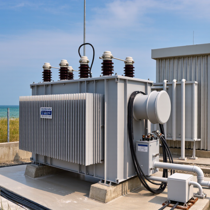
How to Choose an IEC 60076 Power Transformer?

Identify the IEC 60076 Part: Liquid, Dry-Type, or Special Transformer

How to Choose an IEC 60076 Power Transformer?

Start by identifying the transformer’s construction, not its rating alone. IEC 60076-1 provides general requirements, but the equipment type determines which additional parts matter. A liquid-immersed transformer usually needs attention to IEC 60076-2 for temperature rise, IEC 60076-3 for insulation tests, and IEC 60076-5 for short-circuit withstand. Check the cooling method, insulating liquid, altitude, and expected load profile. A 40 MVA unit in an indoor substation faces different thermal conditions from an outdoor unit near the coast.

Dry-type transformers follow a different path. IEC 60076-11 addresses dry-type design, insulation systems, temperature limits, and routine tests. Confirm the enclosure, ventilation, fire requirements, and installation distance around the windings. Dusty rooms can reduce cooling performance. This detail is often underestimated.

Special transformers require closer classification. Reactors relate to IEC 60076-6, while gas-filled and other specialized designs may use dedicated parts. Loading guidance, sound levels, impulse testing, and wind-turbine applications can involve additional sections. Do not select a part from the product name alone. Review the drawings, data sheet, cooling symbols, and site conditions together. I have seen specifications that looked complete but omitted the actual duty cycle. That gap can change the required thermal design. Verify the latest applicable IEC edition with the project engineer and testing laboratory. Mistakes here are usually quiet at first, then expensive.

How to Choose an IEC 60076 Power Transformer?

Identify the IEC 60076 part: liquid, dry-type, or special transformer

General and test parts — 8
IEC 60076-1, -2, -3, -4, -5, -8, -10 and -18
Liquid-immersed — 3
IEC 60076-7, -13 and -14
Dry-type — 2
IEC 60076-11 and -12
Special designs — 3
IEC 60076-6 reactors, -15 gas-filled transformers and -16 wind turbine transformers

Start with the transformer construction: liquid-immersed or dry-type. Then check the dedicated loading, testing, and application parts. Special equipment such as reactors, gas-filled transformers, and wind turbine transformers requires additional IEC 60076 parts. The applicable edition and project requirements should always be verified before specifying the transformer.

Set the Rated Power in kVA/MVA and 50/60 Hz System Frequency

Choosing an IEC 60076 power transformer starts with its rated apparent power, expressed in kVA or MVA. This value must match the connected load, not only the active power in kW. Power factor, motor starting current, harmonics, and future load growth all affect the selection. A transformer operating continuously near its limit may run hotter and age faster.

Estimate the normal demand, then check peak conditions. For example, a facility with a 720 kW load at 0.9 power factor requires about 800 kVA before adding spare capacity. A practical design may choose a higher rating, but excessive oversizing can increase cost and reduce efficiency during light loading. The right margin depends on measured demand, expansion plans, cooling conditions, and installation altitude.

Frequency also matters. A 50 Hz or 60 Hz system must match the transformer’s design data. Frequency changes the volts-per-hertz ratio, which influences core flux, noise, and temperature. Operating a 50 Hz transformer at 60 Hz with the same voltage is often less demanding magnetically. The reverse can be risky, because lower frequency increases flux. Verify the allowed voltage, frequency, tap range, and derating with qualified engineering documentation. Site data is sometimes incomplete. That deserves a second check.

Match HV/LV Voltage, Vector Group, Taps, and ±2×2.5% Regulation

How to Choose an IEC 60076 Power Transformer?

Selecting an IEC 60076 transformer starts with the actual HV and LV system voltages. Confirm nominal voltage, highest system voltage, frequency, insulation level, and neutral arrangement. A 33/0.415 kV nameplate may still fail if the network requires a different earthing method. Check the site drawings and measured voltage. Measure twice.

The vector group defines phase displacement and winding connection. Dyn11 is common in distribution systems, but it is not automatically correct. Match the existing transformer when paralleling units. Confirm phase sequence, neutral availability, impedance, and short-circuit requirements. A wrong vector group can create circulating current or an unusable secondary supply. CIGRE Technical Brochure 642 identifies transformer accessories, windings, and bushings among recurring reliability concerns, supporting stricter commissioning checks.

Tap settings deserve equal attention. The designation ±2×2.5% normally provides five positions: -5%, -2.5%, nominal, +2.5%, and +5%. Confirm whether the tap changer is off-circuit or on-load. Never change an off-circuit tap while energized. Select the tap from measured voltage conditions, not assumptions. Load power factor and transformer impedance also affect delivered LV voltage.

This matters as grids become busier. The IEA Electricity 2024 report forecast global electricity demand growth of about 4% in 2024. The U.S. Department of Energy’s Distribution Transformers Technical Support Document estimated distribution transformer losses at roughly 2.5% of U.S. electricity consumption. A precise voltage ratio, suitable vector group, and realistic tap range can reduce operational waste. The specification may still need revision after site measurements. That is normal engineering.

Check 4–12% Impedance, Fault Duty, and Short-Circuit Withstand

Choosing an IEC 60076 power transformer begins with impedance, but 4–12% is not an automatic answer. This range appears in many distribution projects. However, system voltage, transformer rating, and network strength matter more. A 6% unit may reduce voltage drop during normal loading. It can also increase available fault current. A 10% unit may limit that current. Yet, it may create greater voltage variation. The best value depends on both operating performance and protection design.

Calculate the prospective short-circuit current at the transformer terminals and downstream bus. Include cable length, source impedance, and the actual breaker clearing time. Do not compare impedance values without using the same rating base. For parallel transformers, verify ratio, vector group, tap position, and impedance tolerance. Small mismatches can produce circulating current. Field reviews often reveal a changed result after correcting cable data. That detail is easy to miss.

Short-circuit withstand is not proven by impedance alone. Review thermal and mechanical withstand for the specified fault duration. IEC 60076-5 provides an important reference for this assessment. Request design calculations, test documentation, and clear fault-duty assumptions. Specify the fault level, clearing time, earthing arrangement, and expected network growth. A conservative choice is not always the safest choice. I would recheck every assumption when the network model remains incomplete.

Verify IEC 60076 Tests, 40°C Ambient, Cooling, and Temperature Rise

How to Choose an IEC 60076 Power Transformer?

A reliable selection starts with verified IEC 60076 testing, not a polished datasheet. Request routine test reports, type test evidence, and any agreed special tests. Check the IEC 60076 edition used. Also review calibration dates, test equipment accuracy, tap position, and measurement conditions. Small gaps matter.

Confirm the transformer’s cooling method against the actual installation. ONAN, ONAF, and other arrangements produce different loading capabilities. At a 40°C ambient temperature, available capacity may reduce. Ask for the specified continuous rating at this condition. Inspect the cooler control logic, fan redundancy, alarm settings, and airflow assumptions. A quiet fan room can hide a serious thermal problem.

Temperature rise deserves close attention. Verify how winding and top-oil temperatures were measured during the heat-run test. Compare the reported values with the applicable IEC 60076 limits and the agreed insulation system. Review the test duration, stabilized readings, load losses, and correction method. Do not compare numbers from different ambient conditions without adjustment. I have seen reviews focus on the final temperature while ignoring blocked radiator airflow. That approach is incomplete. Site dust, solar heating, enclosure walls, and altitude can change performance. A factory result is useful, but it is not the whole installation. Ask for the thermal design margin in writing.

How to Choose an IEC 60076 Power Transformer? - Verify IEC 60076 Tests, 40°C Ambient, Cooling, and Temperature Rise

Selection Dimension Typical IEC 60076 Requirement or Data What to Verify in the Technical Specification Selection Guidance
Applicable standard IEC 60076-1 General requirements
IEC 60076-2 Temperature rise for liquid-immersed transformers
IEC 60076-3 Insulation levels and dielectric tests
IEC 60076-5 Short-circuit withstand capability
Confirm the transformer type, rated power, voltage class, insulation system, cooling method, and the editions of the standards used for design and testing. The purchase specification should identify every applicable part of the IEC 60076 series rather than only stating “IEC 60076 compliant.”
Rated voltage and insulation level IEC 60076-3 coordinates power-frequency withstand voltage, lightning impulse withstand voltage, and, where applicable, switching impulse withstand voltage with the highest voltage for equipment. Verify:
  • Rated voltage and highest voltage for equipment
  • Neutral insulation and terminal insulation
  • AC withstand test level
  • Lightning impulse test level and polarity
  • Required external clearances and creepage distances
Select insulation levels according to the system voltage, neutral grounding method, lightning exposure, switching conditions, and installation altitude.
40°C ambient design basis For a conventional IEC liquid-immersed transformer, 40°C is commonly used as the maximum ambient air temperature reference in the temperature-rise calculation. The exact ambient profile must be stated in the project specification. Confirm:
  • Maximum ambient air temperature: 40°C, unless otherwise specified
  • Daily average and annual average ambient temperature
  • Installation altitude and ventilation conditions
  • Indoor or outdoor installation
  • Solar radiation, enclosure effects, and local heat sources
Do not treat 40°C as the only environmental condition. A higher altitude, poor ventilation, or a hotter enclosure can require derating or a different cooling arrangement.
Cooling designation IEC cooling codes identify the internal and external cooling media and the circulation method:

ONAN Oil natural, air natural
ONAF Oil natural, air forced
OFAF Oil forced, air forced
ODAF Oil directed, air forced
AN Air natural, for dry-type transformers
AF Air forced, for dry-type transformers
Verify the rated power available in each cooling stage, fan and pump redundancy, control logic, alarm/trip settings, auxiliary supply, noise impact, and operation after a fan or pump failure. Choose natural cooling for simpler operation and lower auxiliary consumption. Use forced cooling when the required continuous rating, site conditions, or overload profile exceeds the natural-cooling capability.
Temperature-rise limits Under commonly specified IEC liquid-immersed transformer conditions with a 40°C maximum ambient, typical reference limits are:

60 K top liquid temperature rise
65 K average winding temperature rise

The applicable IEC edition, insulation system, cooling mode, and project requirements govern the final values.
Verify whether the guaranteed values are measured or calculated, where the reference temperatures are taken, and whether the limits apply at the principal tap, rated power, and each cooling stage. At 40°C ambient, a 60 K top-liquid rise corresponds to approximately 100°C top-liquid temperature. This is a reference calculation, not a substitute for the guaranteed design values.
Hot-spot temperature The winding hot-spot temperature is higher than the measured average winding temperature. It depends on the winding gradient, load current, cooling arrangement, and transformer thermal design. Request the guaranteed hot-spot temperature or hot-spot rise, the thermal model or calculation method, and the alarm/trip settings for the winding temperature indicator. Hot-spot performance is important for insulation ageing, emergency loading, and expected service life. Do not evaluate the transformer using top-liquid temperature alone.
Routine tests Routine tests commonly include:
  • Winding resistance measurement
  • Voltage ratio and phase displacement verification
  • Short-circuit impedance and load-loss measurement
  • No-load loss and no-load current measurement
  • Applied voltage withstand test
  • Induced voltage withstand test
  • Partial-discharge measurement where specified
Require certified routine-test reports for each transformer, with test temperature, tap position, correction method, measured values, tolerances, and instrument traceability. Compare measured losses and impedance with the guaranteed values and permitted IEC tolerances. Confirm that the test voltage and frequency are appropriate for the insulation design.
Type tests Depending on the design and specification, type tests can include:
  • Temperature-rise test
  • Lightning impulse test
  • Sound-level measurement
  • Zero-sequence impedance measurement
  • Short-circuit withstand test
Verify that type-test evidence applies to the same or a technically representative design, including voltage ratio, rated power, winding arrangement, core construction, impedance, insulation system, and cooling method. A type-test report from a different design should not automatically be accepted as evidence for the proposed transformer.
Special tests Special tests may include:
  • Zero-sequence impedance
  • Capacitance and dissipation factor
  • Frequency-response analysis
  • Transient or transferred-voltage tests
  • Vacuum pressure or tank leak tests
  • Sound-level verification under specified operating conditions
List every required special test in the purchase specification, including test method, acceptance criteria, test tap, cooling stage, and whether the test is factory or site based. Special tests are particularly useful for critical substations, long cable connections, parallel operation, high lightning exposure, or transformers requiring condition-monitoring baselines.
Losses and efficiency Transformer losses consist mainly of no-load loss and load loss. No-load loss is primarily related to core excitation, while load loss varies with current and includes winding resistance and additional stray losses. Verify guaranteed no-load loss, load loss at the specified reference temperature, auxiliary power consumption, impedance tolerance, and the capitalization or evaluation method used for losses. Compare total ownership cost rather than purchase price alone. Low losses can reduce operating cost throughout the transformer’s service life.
Short-circuit withstand IEC 60076-5 addresses the ability of windings and structural components to withstand the thermal and dynamic stresses produced by external short circuits. Confirm system short-circuit level, fault duration, winding connection, neutral arrangement, peak asymmetrical current, and evidence of design verification. The transformer impedance and mechanical design must be compatible with the network fault level. Protection settings should limit fault duration to the specified design basis.
Tap changer and voltage regulation Tap arrangements may be off-circuit or on-load. The specified tap range, step size, and tap position affect the voltage ratio, losses, impedance, and operating voltage. Verify tap range, number of steps, rated current, control voltage, interlocks, position indication, withstand level, and whether the ratio and impedance tests cover all required tap positions. Use an on-load tap changer where voltage regulation is required during energised operation. Use an off-circuit tap changer only when de-energised adjustment is acceptable.
Installation altitude and derating Reduced air density at high altitude decreases the effectiveness of air cooling and reduces external insulation withstand capability unless the design is suitably adjusted. State site altitude, maximum ambient temperature, cooling-air conditions, and required altitude correction for insulation clearances and temperature rise. A transformer designed for sea-level conditions may require derating, larger radiators, stronger forced cooling, or increased clearances at high altitude.
Factory documentation A complete technical file should include the rating plate, approved drawings, guaranteed data, routine-test reports, type-test evidence where applicable, installation instructions, and maintenance requirements. Check that documents identify the transformer serial reference, winding connections, tap positions, cooling stages, test conditions, measured results, and applicable IEC standards. Do not release the transformer for shipment until the documentation is reviewed against the approved specification and all deviations are formally closed.
Final selection checkpoint A suitable transformer should satisfy the electrical rating, insulation level, cooling capacity, 40°C ambient basis, temperature-rise limits, loss guarantees, short-circuit duty, environmental conditions, and testing requirements. Confirm the following:
  • Rated power and voltage match the network
  • Cooling stage supports the required continuous load
  • 40°C ambient and site conditions are included
  • Temperature-rise guarantees are clearly stated
  • IEC routine and required type or special tests are defined
  • Protection, accessories, and maintenance provisions are compatible
Select the design that meets the complete operating duty and verification plan—not merely the nameplate rating.
Reference table for preliminary transformer selection. Final values and acceptance criteria must be confirmed against the applicable IEC 60076 edition, the project specification, utility requirements, and the transformer manufacturer's certified design documentation.
Important: Temperature-rise values, insulation levels, test sequences, tolerances, and cooling-stage ratings are design- and application-dependent. The values shown above are commonly used reference points and must not replace the approved technical specification.

FAQS

How should a transformer’s rated power be selected?

Match the rating to apparent power, measured in kVA or MVA. Include power factor, motor starting current, harmonics, and future expansion. Do not size from kW alone.

How can a 720 kW load at 0.9 power factor be estimated?

Divide 720 kW by 0.9 to obtain about 800 kVA. Add practical spare capacity after checking peak demand and growth plans. The estimate may still be incomplete.

Is choosing a much larger transformer always safer?

No. Oversizing can raise purchase costs and reduce light-load efficiency. A heavily loaded transformer may run hotter and age faster. The margin should reflect measured demand and cooling conditions.

Why must system frequency match the transformer design?

The system must operate at 50 or 60 Hz as specified. Frequency changes the volts-per-hertz ratio, affecting flux, noise, and temperature. Check voltage and frequency together.

Can a transformer designed for 50 Hz operate at 60 Hz?

It may be less demanding magnetically at the same voltage. However, verify the allowed frequency, voltage, tap range, and derating. Never rely on a quick assumption.

What does transformer impedance affect?

Impedance influences voltage drop and available fault current. A lower value may improve voltage regulation but increase fault current. A higher value may limit current but cause greater voltage variation.

Is 4–12% impedance suitable for every project?

No. That range is only a common reference. The correct value depends on voltage, transformer rating, network strength, and protection design. The number alone is not enough.

What information is needed to calculate fault current?

Include source impedance, cable length, transformer impedance, and breaker clearing time. Calculate current at the transformer terminals and downstream bus. Small cable-data errors can change the result.

What must be checked before operating transformers in parallel?

Verify voltage ratio, vector group, tap position, impedance, and tolerance. Mismatches can create circulating current between units. Field data deserves another review.

Does impedance alone prove short-circuit withstand?

No. Review thermal and mechanical withstand for the specified fault duration. Request calculations, test documents, fault levels, and clearing-time assumptions. An incomplete network model needs careful rechecking.

Conclusion

Choosing the right IEC 60076 Power Transformer starts with identifying the appropriate standard part and transformer type. Determine whether the application requires a liquid-immersed, dry-type, or special-purpose transformer, then define the rated power in kVA or MVA and the system frequency, typically 50 or 60 Hz. The high-voltage and low-voltage ratings must match the network, while the vector group, tap arrangement, and voltage regulation range, such as ±2 × 2.5%, should suit the load and grid requirements.

Next, evaluate the transformer’s performance and installation conditions. Confirm that the impedance, commonly within a 4–12% range, is suitable for fault-current control and system coordination. Check short-circuit withstand capability, required IEC 60076 tests, cooling method, and temperature-rise limits. The design should also account for a 40°C ambient temperature and the expected operating environment. A complete review of these factors helps ensure reliable operation, safe protection coordination, and long-term service performance.


Olivia

Olivia

Olivia is a professional marketing specialist dedicated to helping businesses better understand innovative products, evolving market trends, and practical solutions for sustainable growth. With extensive knowledge of the company’s product portfolio, she combines industry insight, customer......