Explore our state-of-the-art range of oil-immersed, dry-type, pad-mounted, and specialized neutral earthing transformers manufactured strictly to IEC 60076, IEEE C57.32, and ISO 9001 standards.
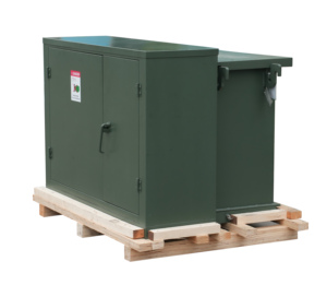
Heavy-duty outdoor pad-mounted unit designed for urban networks and rural utility grid grounding. Tamper-resistant enclosure with dead-front operation.
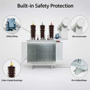
High-efficiency 30kVA–3000kVA 3-phase power transformer featuring 100% electrolytic copper foil windings and step-lap CRGO core for low loss utility grids.
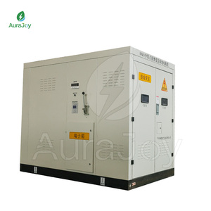
Complete neutral earthing system integrated with a stainless steel Neutral Grounding Resistor (NGR) cabinet for fast single-phase-to-ground fault protection.
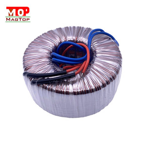
Ultra-low noise, high-frequency toroidal transformers designed for auxiliary power control modules, protection relay circuits, and signal amplification.
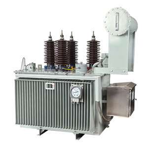
Medium-voltage continuous auxiliary power plus short-time neutral grounding transformer engineered specifically for large-scale solar and wind plants.
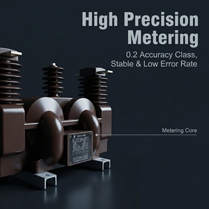
High-precision 10kV indoor instrument transformer with residual voltage winding dedicated to earth fault voltage measurement and system relay protection.
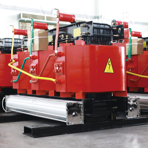
Fire-resistant, flame-retardant dry-type neutral earthing transformer for indoor substations, commercial complexes, data centers, and underground mining networks.
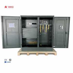
Integrated multi-function unit engineered for dual step-up/step-down transformation and artificial neutral point establishment in ungrounded 10kV–35kV grids.
In ungrounded delta electrical systems (such as 10kV, 22kV, and 35kV medium-voltage distribution networks), single-phase-to-ground faults can create severe arcing grounds, transient overvoltages up to 300%, and equipment insulation breakdown. A grounding transformer creates an artificial, stable neutral point to safeguard electrical assets.
The interstar (Zig-Zag) winding configuration splits each phase into two equal sections wound on separate core limbs. Zero-sequence currents flow in opposite magnetic directions, effectively canceling out core flux and providing an ultra-low zero-sequence resistance route directly back to the system neutral.
Because neutral earthing transformers primarily function during fault conditions, they are sized according to short-time thermal ratings (typically 10 sec, 30 sec, or 60 sec at full ground-fault current $I_k$). This optimizes footprint and structural steel volume while maintaining absolute grid safety.
Modern substations frequently specify secondary star windings ($yn$) on the grounding transformer. This dual-purpose design provides an artificial neutral point while simultaneously supplying continuous 400V station auxiliary power for cooling fans, relays, and lighting circuits.
| Transformer Topology | Core Winding Configuration | Zero-Sequence Impedance ($Z_0$) | Auxiliary LV Power Option | Primary Application Profile |
|---|---|---|---|---|
| Zig-Zag (Zn) Grounding Transformer | Interstar twin-limb cross-coupled coils | Extremely Low ($Z_0 \approx X_{leakage}$) | Optional (Znyn11) | MV Distribution, Renewable PV/Wind Substations |
| Star-Delta (Ynd) Grounding Bank | Star primary with closed delta secondary | Medium-Low (governed by delta circulating current) | No (Delta closed loop) | High-Voltage Utility Grid Substations (66kV+) |
| Dry-Type Cast Resin Grounding Unit | Epoxy encapsulated interstar coils | Tailored per NGR resistance spec | Yes (400V auxiliary output) | Indoor Substations, Metro Rail, Underground Mines |
| Hermetically Sealed Oil Grounding Unit | Step-lap CRGO core in mineral/ester oil | Customized zero-sequence reactance | Yes (ONAN / ONAF cooling) | Outdoor Substation Skids, Harsh Desert/Coastal Grids |
As global energy grids undergo rapid decarbonization, power equipment buyers must anticipate shifts in digital grid compliance, eco-friendly dielectric fluids, and integrated skid substation designs.
Procurement mandates across Europe, North America, and Australia increasingly demand synthetic and natural ester liquids (such as FR3) over conventional mineral oil. Ester fluids raise the flash point above 300°C, providing self-extinguishing safety for solar farms located in high-risk arid environments.
Next-generation grounding transformers incorporate optical fiber winding temperature sensors, continuous zero-sequence current monitoring, online Dissolved Gas Analysis (DGA), and Modbus/IEC 61850 communication gateways for predictive grid maintenance.
EPC contractors are moving away from piecemeal procurement. Modern buyers request factory-tested, integrated skids comprising the Grounding Transformer, Neutral Grounding Resistor (NGR), Neutral CT, Isolation Disconnector, and Surge Arrester inside a single IP55 outdoor housing.
Operating from a 103,500+ sq. ft. modern manufacturing plant with dedicated core-cutting, automated foil winding, vacuum pressure impregnation (VPI), and high-voltage testing laboratories.
Get expert answers regarding grounding transformer sizing, neutral resistor matching, vector group selection, and international factory delivery options.
The kVA rating of a grounding transformer is determined by the system line-to-neutral voltage ($V_{ln}$) and the designated short-time neutral fault current ($I_n$) for a specified duration (typically 10 to 60 seconds). The equation is:
$\text{kVA} = \frac{V_{ll} \times I_n}{\sqrt{3}}$
If an auxiliary secondary winding is included to supply continuous substation load, the continuous auxiliary load kVA is added vectorially to the short-time thermal rating requirements.
A Zig-Zag transformer is significantly more compact and cost-effective for dedicated grounding applications. Because the zero-sequence currents in the opposite halves of the windings on the same core limb flow in opposite directions, the core flux cancels out. This yields an extremely low zero-sequence impedance without needing a secondary delta winding, reducing copper and core steel volume by 20% to 30% compared to a Ynd bank.
The NGR is connected between the artificial neutral point of the grounding transformer and earth. The NGR limits the maximum earth fault current (e.g., to 10A, 50A, 100A, or 400A) to prevent stator core burning in generators and minimize transient arc overvoltages. The grounding transformer's zero-sequence reactance ($X_0$) must be matched to the resistor value ($R_n$) so that $X_0 \le R_n$ to suppress arcing ground overvoltages effectively.
All designs are engineered and routine-tested in accordance with international standards including IEC 60076-6 (Reactors & Grounding Transformers), IEEE C57.32 (Requirements for Neutral Grounding Devices), ANSI/IEEE Std 32, and GB 1094. Type test certificates from independent laboratory bodies (e.g., KEMA, CNAS) are available upon request.
Yes. We manufacture epoxy resin vacuum cast (VPI / CRT) dry-type grounding transformers ranging from 100kVA up to 2500kVA for voltage classes up to 35kV. These units feature Class H insulation (180°C), self-extinguishing F1 fire performance, and E2/C2 environmental withstand ratings, making them ideal for high-rise buildings, underground subways, and off-shore substations.
Standard design distribution and grounding transformers are manufactured within 3 to 4 weeks after engineering drawing approval. Custom power grounding transformers with integrated NGR cabinets or specialized multi-winding auxiliary loads typically require 5 to 7 weeks. We provide seaworthy packaging, container loading, and complete customs clearance documentation worldwide.
Consult directly with our senior transformer application engineers to receive custom single-line diagram (SLD) reviews, technical proposals, and factory-direct pricing within 24 hours.
Get a Quote