Explore our custom OEM transformer lineup engineered for sub-station step-down, solar/wind inverter duty, industrial plants, and utility battery energy storage system (BESS) integration.
As global energy transitions accelerate, utility-scale Battery Energy Storage Systems (BESS), solar-plus-storage microgrids, and decentralized distribution networks require specialized magnetics capable of handling bi-directional power flows, rapid thermal cycling, and complex harmonic spectra generated by multi-megawatt central inverters. Standard utility distribution transformers are frequently ill-equipped for the extreme dynamic loading, voltage THD (Total Harmonic Distortion), and continuous DC bias currents inherent to modern battery storage power conversion systems (PCS).
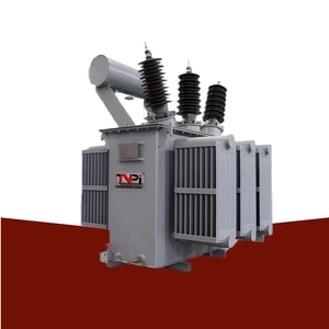
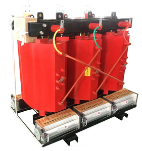
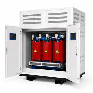
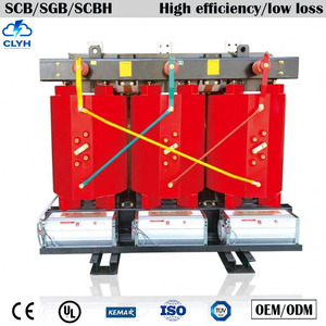
As a specialized OEM energy storage manufacturer and global exporter originating from Rajkot, Gujarat, India, Synergy Transformers Pvt. Ltd. (operating since 2004) manufactures custom-engineered step-up and step-down power transformers, cast resin dry-type isolation units, multi-winding inverter duty transformers, and compact secondary substations (CSS) tailored precisely to global OEM integration standards.
Information Gain Key Takeaway: Energy storage transformers require K-factor rated core-and-coil topology, multi-split low voltage (LV) windings to isolate parallel inverter channels, advanced electrostatic shielding, and continuous foil winding to mitigate axial short-circuit forces caused by rapid grid transient response.
Under our ISO-compliant quality system, Synergy Transformers operates a fully integrated 103,500+ sq. ft. manufacturing facility spanning over 131,500 sq. ft. of total land area in Rajkot. Every critical production phase—from precision CRGO (Cold Rolled Grain Oriented) core cutting and step-lap lamination stacking to automated foil winding, tank fabrication, surface treatment, and oil processing—takes place under one roof under the oversight of 70+ skilled power system engineers and specialists.
Eliminates transposition joints, distributes axial short-circuit forces uniformly across the coil length, drastically lowers hot-spot temperatures, and enhances dielectric endurance under peak inverter load steps.
Utilizes prime-grade, high-permeability silicone steel laminations with automated step-lap miter joints to minimize no-load losses ($P_0$), lower magnetizing current, and dampen acoustic noise emission levels.
100% routine verification per IS 1180, IS 2026, and IEC 60076 standards, including turns ratio, vector group validation, winding resistance, insulation resistance ($R_{15}/R_{60}$), load loss, and impulse voltage withstand testing.
Strategic sourcing directors and EPC consultants are shifting procurement specifications to accommodate next-generation energy storage architectures. The following industry macro-trends govern forward-looking procurement requirements:
To reduce balance-of-plant (BOP) expenditures, modern utility-scale energy storage plants link multiple central inverters (up to 4 separate channels) to a single step-up transformer. This mandates custom OEM designs featuring split-LV windings (e.g., Dy11y11 or Dy11y11d11) with strict magnetic decouplings to prevent inter-inverter circulating currents and cross-talk harmonics.
Traditional mineral oil insulation is increasingly superseded by natural or synthetic ester fluids (K-class fluids with fire points >300°C) in urban, sub-surface, and environmentally sensitive BESS installations. Ester fluids offer superior fire safety, high thermal tolerance, and 100% biodegradability without compromising dielectric strength.
Future-ready BESS transformers incorporate real-time Fiber-Optic Temperature Sensors (FOTS) positioned directly within the LV winding hot-spots, Online Dissolved Gas Analysis (DGA) monitors, dynamic load rating sensors, and moisture-in-oil telemetry integrated into central Supervisory Control and Data Acquisition (SCADA) networks.
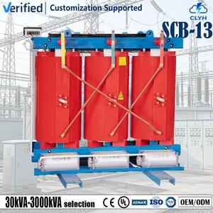
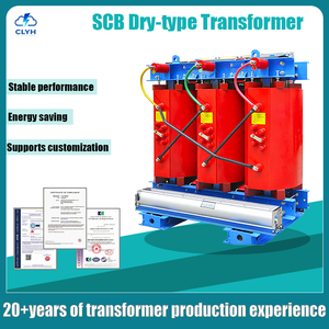
For indoor commercial and industrial (C&I) battery energy storage systems, cast resin dry-type transformers compliant with IEC 60076-11 (F1 fire resistance, E2 environmental durability, C2 climate endurance) are fast becoming mandatory to fulfill stringent municipal fire codes and insurance underwriting conditions.
Selecting the optimal transformer topology depends on site ambient conditions, safety class requirements, installation footprint, and harmonic loading parameters. Below is a comparative technical overview for OEM procurement teams:
| Feature / Parameter | Oil-Immersed Distribution (IS 1180) | Cast Resin Dry-Type (IEC 60076-11) | Multi-Winding Inverter Duty (BESS) | Compact Substation Kiosk (CSS) |
|---|---|---|---|---|
| Power Rating Envelope | 16 kVA – 3150 kVA | 100 kVA – 4500 kVA | 500 kVA – 3500 kVA | 250 kVA – 2500 kVA |
| Max Voltage Class | Up to 33 kV | Up to 33 kV | Up to 33 kV / 69 kV | 11 kV / 22 kV / 33 kV |
| Cooling Medium | ONAN / ONAF Mineral or Ester Oil | AN / AF Forced Air Cooling | ONAN / ONAF Liquid Immersed | Self-Ventilated IP-Rated Enclosure |
| Harmonic Capability | Standard Utility Loads | K-4 to K-13 Rated Options | High K-Factor (K-13 to K-20) | Application Tailored |
| Fire & Safety Rating | Standard Outdoor Clearances | F1 Self-Extinguishing, Zero Toxic Gas | Enhanced Ester Fluid Safety | Vandal Proof, Weatherproof Shell |
| Primary Application | Feeders, Utilities, Substation Step-Down | Hospitals, Metros, Data Centers, Malls | BESS Battery Storage, Solar & Wind Step-Up | Plug & Play Remote Sites, Urban Grid |
As battery energy storage units transition from short-duration frequency regulation to long-duration energy arbitrage (4 to 8+ hours), the operational duty cycle imposed on step-up and step-down transformers changes dramatically. Key engineering developments include:
Unlike conventional continuous-duty power transformers that experience gradual daily thermal shifts, BESS transformers undergo steep thermal gradients during rapid full-power charge and discharge sequences. Synergy’s engineering team utilizes proprietary thermal modeling algorithms to design high-density insulating pressboard clamping structures, uniform cooling oil ducts, and reinforced coil bracing capable of absorbing tens of thousands of thermal cycles over a 25-year operational lifecycle without mechanical insulation degradation.
Pulse-width modulated (PWM) solid-state inverters introduce high-frequency current harmonics that induce stray losses in transformer tanks, core frames, and winding conductors. By implementing fine-element electromagnetic analysis (FEA), shielded multi-layer foil windings, and segmented core geometries, Synergy custom OEM transformers restrict eddy current losses ($P_{ec}$) and stray load losses ($P_{os}$), ensuring operation well within energy efficiency limits specified under IS 1180 Level 1 / Level 2 and international IEC standards.
A: Energy storage transformers are specifically engineered to withstand bi-directional power flows, rapid thermal cycling, DC offset currents from inverters, and high current harmonics (high K-factor duty). They frequently feature electrostatic shields between primary and secondary windings, multi-split low voltage coils (to isolate independent inverter channels), and reinforced mechanical clamping to handle frequent grid fault responses.
A: We custom design vector groups based on your power conversion system (PCS) specification. Common vector configurations include Dy11, Dy11y11 (dual LV), Dy11y11d11 (triple LV), and custom phase-shifted topologies (such as Dy11d0) designed to achieve 12-pulse or 24-pulse harmonic cancellation across the inverter system.
A: All transformers manufactured by Synergy comply with IS 1180, IS 2026, and IEC 60076 standards (and IEC 60076-11 for cast resin units). Every unit undergoes 100% routine testing at our Rajkot factory. Export dossiers include certified general arrangement (GA) drawings, nameplate layouts, routine test certificates, guaranteed technical particulars (GTP), O&M manuals, and raw material mill test reports (MTR) for CRGO and conductor coils.
A: Foil winding uses full-width copper or aluminum sheets, which eliminates axial mechanical forces during severe external short circuits. It creates a balanced electrical stress distribution across the coil height, eliminates high thermal hot-spots, improves heat dissipation, and drastically increases the operating life of the transformer insulation under heavy cyclic loading.
A: Standard distribution transformers require approximately 3 to 5 weeks following GA drawing approval. Custom utility-scale power transformers, multi-winding inverter duty units, and compact substations generally require 6 to 10 weeks depending on rating and tap-changer complexity. Overseas client engineering teams or appointed third-party inspection agencies (e.g., Bureau Veritas, SGS, TUV, Intertek) are fully welcome to witness factory acceptance testing in our Rajkot test bay.
A: Export units receive seaworthy heavy-duty wooden crate packaging, nitrogen blanket charging for un-oiled main tanks during transit (when required), high-integrity corrosion-inhibiting vacuum wrapping, silica gel desiccant packs, and heavy-duty steel skid bases designed for safe container loading and crane rigging at destination ports.
Whether you require custom step-down distribution units, cast resin dry-type isolation transformers, or multi-winding battery storage step-up packages, our technical presales team in Rajkot, India is ready to assist your procurement team.
