Rigorously tested to IEC 60076, IS 2026, and IEEE standards. Engineered for grid resilience, extreme climate endurance, and minimal total operational cost.
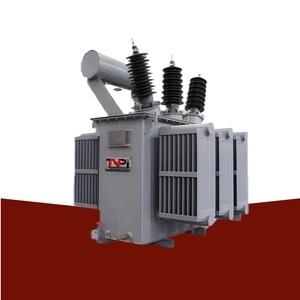
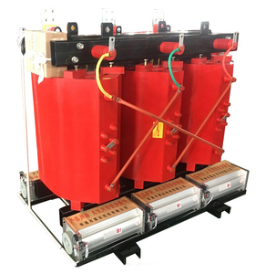
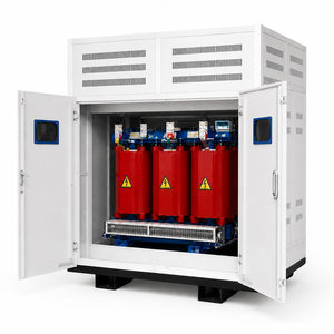
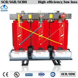
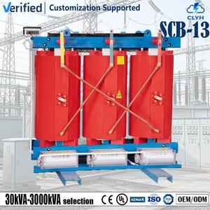
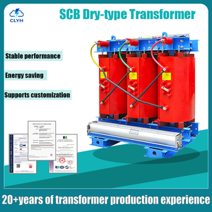
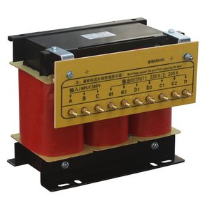
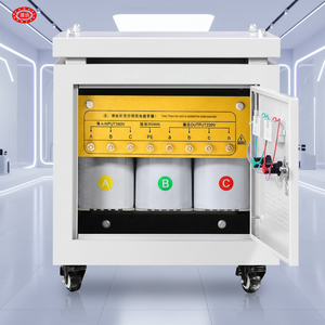
As global power grids undergo a seismic shift toward carbon neutrality, energy efficiency metrics for power distribution assets are subject to stringent regulatory enforcement. Electrical utility engineers, industrial procurement leaders, and EPC directors face an escalating mandate: reduce passive network operational losses without sacrificing transformer short-circuit withstand capabilities or long-term operational lifespan. Central to this technological transformation is the deployment of Amorphous Alloy Core Transformers (AMDT) and advanced Cast Resin Dry-Type Isolation Units engineered through custom OEM/ODM manufacturing partnerships.
The primary driver behind the adoption of amorphous cores in step-down distribution networks is the severe mitigation of no-load (iron) losses ($P_0$). In conventional transformers, no-load losses occur continuously 24 hours a day, 365 days a year, regardless of whether the secondary side is supplying heavy industrial loads or remaining under light overnight conditions.
Amorphous alloys—primarily composed of Iron, Silicon, and Boron ($Fe_{78}Si_9B_{13}$)—are fabricated into ultra-thin ribbons approximately 25 microns ($0.025\text{ mm}$) thick. In comparison, top-tier cold-rolled grain-oriented silicon steel sheets measure approximately $0.23\text{ mm}$ to $0.27\text{ mm}$. Because eddy current loss ($P_e$) is proportional to the square of the material thickness ($P_e \propto t^2$), the ultra-thin dimension of amorphous foil curtails eddy current dissipation to near negligible thresholds.
Random atomic structure requires minimal coercive force ($H_c$) for magnetic domain orientation, dramatically compressing the $B-H$ loop area and preventing energy dissipation as ambient heat.
High-precision foil winding technology replaces wire turns, balancing axial electrodynamic short-circuit forces uniformly and eliminating hot-spot temperature gradients in the LV coil.
Operates at substantially reduced internal temperatures under rated loads, preserving Class F and Class H insulation integrity and extending asset service life to 30+ years.
Selecting the proper transformer architecture requires balancing capital expenditure (CAPEX), operational losses (OPEX), space constraints, environmental safety, and thermal dissipation profile. Below is an engineering specification reference matrix comparing core metallurgical choices and dielectric insulation designs:
| Performance Parameter | Amorphous Alloy Core (Oil Immersed) | CRGO Silicon Steel (Oil Immersed) | Cast Resin Dry-Type (SCB Epoxy) |
|---|---|---|---|
| Core Material & Thickness | Fe-Si-B Metallic Glass (0.025 mm) | M4/M6 Grain Oriented Steel (0.23-0.27 mm) | High-Grade CRGO / Amorphous Hybrid |
| Saturation Flux Density ($B_s$) | ~1.56 Tesla | ~2.03 Tesla | 1.7 - 2.0 Tesla |
| Relative No-Load Loss ($P_0$) | Ultra-Low (20% - 25% of Standard) | Baseline (100% Reference) | Low-to-Medium (Optimized per IEC 60076-11) |
| Short-Circuit Stress Capacity | Special Rectangular Clamping Required | Standard High Strength Assembly | Extreme (Cast Epoxy Rigid Structure) |
| Fire Safety & Environmental Impact | Requires Containment Bunds | Requires Containment Bunds | Self-Extinguishing (F1 Class, Zero Oil) |
| Optimal Application Environment | Rural Distribution, 24/7 Low Load Grids | Heavy Transmission & High Load Plants | Data Centers, Hospitals, Indoor Substations |
As a specialized OEM/ODM transformer factory and international exporter, our manufacturing floor integrates end-to-end component fabrication under a unified ISO 9001, ISO 14001, and ISO 45001 Quality Management System. The production methodology for amorphous and dry-type units involves precise technical execution:
The international electrical procurement landscape is undergoing a structural realignment driven by grid decarbonization, the surge in renewable energy interconnections, and the rapid expansion of hyperscale data centers. Procurement officers must evaluate several macroeconomic and technical trends when selecting an OEM/ODM manufacturing partner:
Harmonic Resilience for Data Centers & Renewables: Non-linear loads originating from solar PV inverters, variable frequency drives (VFDs), and server power supplies introduce high-frequency harmonics (3rd, 5th, 11th, 13th) into the distribution grid. OEM/ODM factories must supply isolation transformers engineered with specific K-factor ratings (K-4, K-13, K-20) featuring electrostatic shielding between primary and secondary windings to bypass common-mode voltage noise to ground.
To guarantee operational reliability in demanding environments—ranging from desert solar farms in the Middle East to humid coastal industrial zones in Southeast Asia—every transformer manufactured in our facility undergoes rigorous factory acceptance testing (FAT) inside our fully calibrated routine test bay.
Routine Test Protocols (100% Batch Inspection):
Type and Special Testing Support: Client-witnessed or third-party (SGS, TÜV, Intertek, Bureau Veritas) testing is routinely conducted for full Lightning Impulse Voltage Withstand Tests, Temperature Rise Tests (ONAN/ONAF thermal equilibrium), Partial Discharge measurements, and Airborne Sound Level audits per IEC 60076-10 standards.
Because amorphous ribbons are extremely thin and lack the rigid structural thickness of silicon steel sheets, the core itself cannot serve as a structural load-bearing member for the winding assembly. Our OEM design resolves this by utilizing an independent, heavy-duty rectangular steel clamping frame that absorbs axial and radial electrodynamic forces directly, keeping core stress zero during short-circuit faults.
Amorphous alloys exhibit a slightly higher magnetostriction coefficient than CRGO steel, which can lead to a 3 dB to 5 dB increase in acoustic sound level if untreated. However, through structural vibration damping, flexible core cushioning, and magnetic field annealing, our factory controls sound emission levels well within strict NEMA ST-20 and IEC noise threshold standards.
Yes. We specialize in custom ODM engineering for international exporters. We routinely manufacture dual primary or secondary voltages (e.g., 11kV / 22kV switchable primary, 400V / 415V / 480V secondary) equipped with multi-position off-circuit tap changers (OCTC) or automatic on-load tap changers (OLTC).
Every export dispatch includes a comprehensive technical dossier: Certified General Arrangement (GA) drawings, Nameplate schematics, Guaranteed Technical Particulars (GTP), Type Test reports from accredited laboratories, Routine Test certificates signed by quality directors, Operation & Maintenance (O&M) manuals, and seaworthy packing lists.
Standard distribution transformers (100kVA to 3150kVA) typically require 3 to 4 weeks after GA drawing sign-off. High-capacity power transformers (up to 30MVA / 69kV) or specialized cast resin units usually require 6 to 8 weeks, inclusive of complete routine testing and seaworthy export packaging.
Submit your Single-Line Diagrams (SLD), tender specifications, or custom capacity requirements directly to our engineering desk for immediate technical review and competitive factory pricing.
