
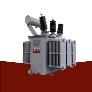
Explore our engineering-grade oil-immersed and cast resin transformers, manufactured under strict IS 1180, IS 2026, and IEC 60076 quality frameworks.
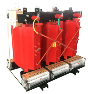
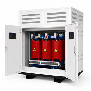
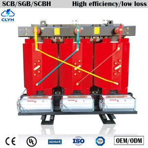
Operating from Rajkot, Gujarat since 2004, our vertically integrated plant delivers certified electrical infrastructure engineered to survive extreme electrical stresses and harsh ambient conditions.
Unlike conventional round wire winding, our continuous copper and aluminum foil winding technology completely eliminates mechanical transposition points. This distributes axial short-circuit electromagnetic forces uniformly along the entire coil surface, drastically minimizing radial displacement during severe grid fault conditions while dramatically lowering hot-spot temperature rise.
We strictly engineer every OEM/ODM transformer to comply with BIS 1180 (Level 1 and Level 2) energy loss limits and international IEC 60076 efficiency benchmarks. By utilizing high-permeability, cold-rolled grain-oriented (CRGO) silicon steel cores from top-tier mills, we reduce no-load magnetizing losses and overall lifetime operational expenses for plant operators.
Every single unit dispatched from our plant undergoes rigorous routine testing in accordance with IEC 60076 parts 1-11 and IS 2026. Our fully equipped test laboratory executes transformer ratio, vector group verification, winding resistance measurement, insulation power factor, dielectric breakdown testing, and full load/no-load loss verification prior to customer witness clearance.
OEM/ODM Technical Assurance: Every step-up and power transformer engineered at our facility comes complete with verified Type Test records, Guaranteed Technical Particulars (GTP), detailed dimension GA drawings, and full traceability reports for core steel, mineral oil, and conductor batches.
When selecting a high-reliability step-up transformer for solar PV farms, wind turbines, or heavy industrial captive generation, transformer winding topology dictates mechanical durability, thermal endurance, and service lifetime. Standard wire-wound coils rely on layered rectangular or round conductors wrapped in cellulose paper insulation. During direct online grid step-up switching or downstream short-circuit events, extreme axial electromagnetic forces push individual turns against each other, creating stress concentration points that cause mechanical deformation and paper wear over time.
Our OEM/ODM manufacturing process employs advanced continuous foil winding technology. By replacing individual wire conductors with wide sheet copper or aluminum foil insulated by high-grade resin-preimpregnated film, the electrical current distributes uniformly across the full electrical width of the winding cylinder. This construction offers three decisive operational advantages:
Consult our standardized technical parameters for custom power transformers, cast resin dry-type units, inverter duty transformers, and compact secondary substations.
| Transformer Category | Capacity Envelope | Primary Voltage Class | Cooling / Insulation | Applicable Standards |
|---|---|---|---|---|
| Oil-Immersed Step Up Transformer | 100 kVA – 3500 kVA / 30 MVA | 11 kV, 22 kV, 33 kV, 69 kV | ONAN / ONAF, Mineral Oil / Ester | IS 2026, IEC 60076, IEEE C57 |
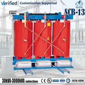
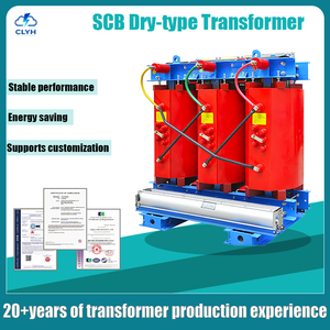
| Cast Resin Dry-Type Transformer | 16 kVA – 4500 kVA | Up to 33 kV Class | AN / AF, Class F / H Insulation | IEC 60076-11, CE Listed |
| Solar / Wind Inverter Duty Unit | 250 kVA – 3150 kVA | 0.4 kV – 33 kV Step Up | Multi-Winding, ONAN, K-Factor 13/20 | IS 1180, IEC 60076, Customized |
| Induction Furnace Transformer | 500 kVA – 10,000 kVA | 11 kV / 33 kV to High-Current LV | ONAN / OFWF Heavy-Duty Busbar | IEC 60076 Series, Custom Heavy Duty |
| Compact Sub Station (CSS Kiosk) | 250 kVA – 2500 kVA | 11 kV / 22 kV / 33 kV | IP54 Enclosure with VCB / RMU / LBS | IEC 62271-202, IS 14786 |
How global decarbonization, renewable power integration, and smart grid mandates are shaping transformer engineering requirements through 2035.
Traditional mineral oil is rapidly being replaced in high-density urban grids, underground substations, and offshore installations by natural and synthetic ester fluids. Ester liquids feature high fire points (>300°C, Class K), eliminating the need for complex fire deluge systems, and are 100% readily biodegradable within 28 days, preventing soil contamination in environmentally sensitive zones.
Modern EPC tenders increasingly require online Dissolved Gas Analysis (DGA) sensors, fiber-optic real-time hot-spot temperature monitors, and smart Buchholz relays. These digital sensors feed data into cloud SCADA platforms, allowing power utilities to transition from reactive maintenance schedules to predictive condition-based asset management.
As utility-scale solar PV plants transition to high-capacity central inverters (2.5 MW to 5 MW+), procurement managers require multi-winding step-up transformers featuring dual or quad low-voltage inputs. These units require specialized electrostatic shielding between primary and secondary coils to isolate high-frequency switching harmonics and prevent voltage reflection transients.
In modern industrial facilities utilizing variable frequency drives (VFDs), arc furnaces, data center UPS power supplies, and solar inverter stations, electrical current non-linearities create high-order harmonics (primarily 5th, 7th, 11th, and 13th order). Standard distribution transformers operating under high harmonic distortion suffer severe eddy current losses in windings and stray stray-flux heating in structural steel tanks, resulting in premature thermal breakdown of insulation.
As an OEM/ODM step-up manufacturer, our design team calculates specific K-Factor ratings (K-4, K-13, K-20) based on your system harmonic spectrum. We incorporate oversized neutral conductors (200% rated capacity), electrostatic copper shields grounded to the tank, and specially transposed foil conductors. This prevents phase-to-phase magnetic core saturation, controls stray eddy current losses, and guarantees rated KVA delivery without derating or insulation degradation over a 30-year operational life.
From technical specification review to final seaworthy dispatch, every transformer follows a strict quality assurance protocol.
Review of single-line diagrams, voltage ratios, tap ranges, impedance limits, vector groups (Dyn11, Ynd11), and thermal limits using 3D electromagnetic CAD modeling.
Precision 45-degree step-lap shearing of high-grade CRGO silicon steel, coupled with automated high-tension foil and wire winding under cleanroom environments.
Core-coil assembly undergoes deep vacuum thermal drying to eliminate all moisture from paper insulation, followed by total oil impregnation under deep vacuum.
Shot-blasted, leak-tested steel tanks with multi-coat anti-corrosive polyurethane coating, verified by full routine factory acceptance testing (FAT).
Nitrogen-padded or fully oil-filled seaworthy wooden crate packaging with moisture-proof vacuum wrapping for safe global ocean freight delivery.
Get authoritative technical answers to common questions asked by utility managers, EPC procurement officers, and engineering consultants.
Our Rajkot manufacturing facility manufactures both oil-immersed and cast resin dry-type transformers ranging from 16 kVA up to 3500 kVA / 30 MVA in primary voltage classes up to 33 kV and 69 kV. This encompasses distribution transformers, power transformers, induction furnace units, solar/wind inverter step-up units, and compact secondary substations (CSS).
All units are engineered and tested in compliance with IEC 60076 (Power Transformers), IS 2026, and IS 1180 (Energy Efficiency Level 1 & Level 2). Cast resin dry-type units conform to IEC 60076-11 with environmental, climatic, and fire behavior classifications (E2, C2, F1). Compact substations adhere to IEC 62271-202.
Foil winding uses continuous sheet copper or aluminum across the entire coil width. This eliminates axial turns and transposition joints, resulting in equal distribution of short-circuit axial electromagnetic forces, improved radial mechanical strength, lower hot-spot temperature rises, and significantly extended service life during frequent grid fault events.
Yes, we welcome customer witness testing and third-party inspection agencies (such as SGS, Bureau Veritas, TUV, or Intertek) at our Rajkot test bay. We provide approved general arrangement (GA) drawings, Guaranteed Technical Particulars (GTP), and test protocols in advance for seamless FAT verification.
Standard distribution transformers are ready for dispatch within 3 to 5 weeks following drawing approval. Custom power transformers, multi-winding inverter duty units, furnace transformers, and compact substations require 6 to 10 weeks depending on custom tap-changer requirements (OLTC/OCTC) and special bushing accessories.
Export transformers are sealed in heavy-duty, fumigated ISPM-15 compliant seaworthy timber crates. Larger power units are shipped either completely filled with degassed mineral oil or pressurized with dry nitrogen gas equipped with pressure monitoring gauges to prevent moisture ingress during long transit.
ONAN (Oil Natural Air Natural) relies on natural convection of transformer mineral oil through cooling radiator fins dissipated by ambient air currents. ONAF (Oil Natural Air Forced) adds external automated cooling fans to the radiator banks, increasing continuous heat dissipation capacity by up to 25% to 33% during peak power demands without resizing the core or oil volume.
To receive a comprehensive proposal, please provide: rated capacity (kVA/MVA), primary and secondary primary voltages, frequency (50Hz/60Hz), vector group (e.g., Dyn11), tap changer type (off-circuit or on-load), percentage impedance, cooling method (ONAN/AN), target standards (IEC/IS), and ambient site environmental conditions.
Send your project single-line diagram (SLD), tender specifications, or custom equipment requirements to our pre-sales engineering team for a rapid technical proposal and competitive pricing.