

Comprehensive Technical Guide: OEM/ODM Tap Changer Engineering, Selection & Global Procurement Architecture
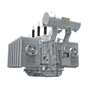
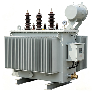
In modern high-voltage electrical distribution and transmission networks, voltage stability is paramount. The voltage profile across distribution networks fluctuates dynamically due to load variations, industrial switching surges, and the intermittent injection of renewable power from photovoltaic (PV) plants and wind farms. The primary apparatus responsible for dynamic voltage regulation is the Tap Changer, integrated directly into power and distribution transformers. As utility companies and Industrial EPC contractors scale up infrastructure, sourcing from verified OEM/ODM Tap Changer Factories & Suppliers who possess deep metallurgical, mechanical, and dielectric engineering capabilities has become a strategic priority.
This industry whitepaper evaluates the engineering architecture of On-Load Tap Changers (OLTC) and De-Energized Tap Changers (DETC / No-Load Tap Changers), explores advanced material selection, outlines key testing protocols according to IEC 60214-1 and IEEE C57.131 standards, and examines global procurement dynamics for utility-scale applications.
Key Procurement Insight: Sourcing OEM/ODM tap changers requires evaluating not only steady-state dielectric withstand voltage but also dynamic contact resistance (DCRM), transition resistance heat dissipation, and mechanical fatigue lifetime under severe cyclic loading.
1. Fundamental Architecture: On-Load Tap Changer (OLTC) vs. De-Energized Tap Changer (DETC)
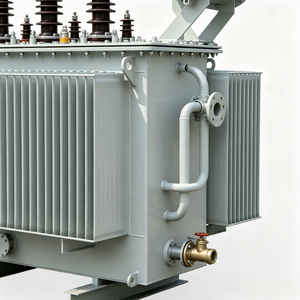
Transformers are equipped with tapped windings (typically located on the High Voltage winding where current is lower, minimizing contact surface requirements). The selection between an On-Load Tap Changer (OLTC) and a De-Energized Tap Changer (DETC) dictates the operating flexibility and overall capital expenditure of a substation installation.
1.1 On-Load Tap Changer (OLTC) Technology
An OLTC allows ratio adjustments—and thus voltage regulation—without interrupting the load current. This is critical for main grid substations, steel furnace feeds, and commercial distribution feeders where power continuity cannot be compromised. The OLTC mechanism comprises two main physical modules: the Diverter Switch (or Selector Switch) and the Tap Selector.
During a tap change operation, the mechanism must transition from tap N to tap N+1 without breaking the main circuit (which would cause massive inductive arcing) and without short-circuiting the tapped turn section (which would create dangerous circulating currents). To achieve this, high-speed diverter switches utilize transition resistors or vacuum interrupters to bridge the adjacent taps temporarily for milliseconds.
- Oil-Break Switching: The arcing occurs directly in transformer oil. While economical, arcing decomposes the mineral oil into carbon particles and dissolved gases (acetylene, ethylene), requiring isolated oil compartments, dedicated conservator tanks, and frequent oil filtration.
- Vacuum-Break Switching: Modern OEM/ODM factories predominantly engineer vacuum interrupter OLTCs. Electric arcing is entirely contained inside hermetically sealed vacuum bottles. Consequently, the dielectric oil remains pristine, maintenance intervals are drastically extended from 50,000 operations to over 300,000 operations, and dissolved gas analysis (DGA) monitoring becomes highly accurate.
1.2 De-Energized Tap Changer (DETC / Off-Circuit / No-Load)
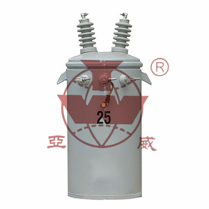
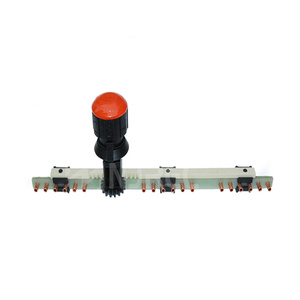
DETCs are operated only when the transformer is fully isolated from the electrical grid. They are primarily utilized in distribution transformers (e.g., 11kV to 0.4kV step-down units) to adjust for seasonal voltage drift or permanent line drop along long rural feeders. DETC mechanisms are mechanically simpler, utilizing rotary or linear bridge contacts held under heavy spring pressure to maintain low contact resistance.
Technical Comparison Matrix: OLTC vs. DETC for OEM/ODM Buyers
| Technical Parameter | On-Load Tap Changer (OLTC) | De-Energized Tap Changer (DETC) |
|---|---|---|
| Operation Mode | Energized under full load current | De-energized (Isolated transformer) |
| Switching Medium | Vacuum interrupter bottle or Mineral/Ester Oil | Air or Transformer Dielectric Fluid |
| Typical Voltage Classes | 11kV, 33kV, 66kV, 110kV up to 500kV | 1.1kV, 11kV, 22kV, 33kV, ≤52kV |
| Regulation Range | ±10% to ±20% in 8, 12, 16, or 32 steps | ±2.5%, ±5% (typically 5 position steps) |
| Drive Mechanism | Motor Drive Mechanism (MDM) + SCADA Automation | Manual Top-Cover / Side-Wall Handwheel |
| Maintenance Interval | 100k - 300k operations (Vacuum type) | Visual inspection during routine shutdowns |
| Primary Application | Substations, Renewables, Steel Mills, Industrial | Commercial distribution, Pole-mounted units |
2. OEM/ODM Customization & Manufacturing Excellence
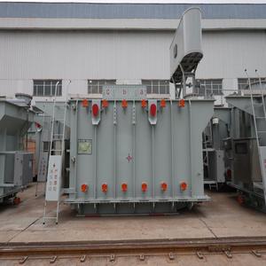
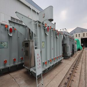
High-capacity transformer facilities—such as Synergy Transformers' 103,500+ sq. ft. manufacturing headquarters in Rajkot, India—demonstrate the engineering depth required to build robust tap-changer-integrated power units. Custom OEM/ODM manufacturing demands total vertical integration, controlling every variable from core steel cutting to high-potential impulse testing.
2.1 Core Cutting & Foil Winding Integration
The mechanical performance of a tap-changer-equipped transformer under short-circuit stress depends heavily on coil alignment. When taps are added to an HV winding, physical gaps are introduced in the winding structure. If not compensated for, these gaps create unbalanced magnetic fields during through-faults, generating extreme axial compression and tension forces that can shear tap leads or crush tap selector contacts.
To overcome this, leading OEM factories implement advanced Foil Winding Technology for Low Voltage coils combined with precision step-lap CRGO (Cold Rolled Grain Oriented) silicon steel core cutting. Foil winding spreads axial electromagnetic forces uniformly along the height of the coil, neutralizing the asymmetrical forces induced when operating at extreme tap positions (+15% or -15%).
2.2 Motor Drive Mechanism (MDM) & Digital SCADA Integration
The reliability of an OLTC relies on its external Motor Drive Mechanism (MDM). Modern smart-grid architectures require MDMs equipped with:
- Absolute Digital Position Encoders: Providing real-time, non-volatile binary or Modbus/IEC 61850 tap position feedback to centralized control rooms.
- Torque Monitoring Sensors: Detecting subtle mechanical resistance variations caused by selector gear wear or contact binding before catastrophic failure occurs.
- Automatic Voltage Regulators (AVR): Integrating digital microcontrollers programmed with line-drop compensation (LDC) algorithms and reverse power flow detection for bidirectional grid tie points.
3. Global Supply Chain & Procurement Trends (2025–2035)
The global market for tap changers and voltage-regulating transformers is undergoing a massive transformation driven by three secular trends: decarbonization, grid modernization, and the electrification of industrial heat and transport.
3.1 Solar and Wind Inverter-Duty Integration
Renewable energy generation presents distinct challenges to traditional voltage regulation equipment. Solar inverters switch at high frequencies, introducing harmonic distortion (THD) and causing rapid power generation ramps during cloud passage. Power transformers situated in solar plants experience tens of thousands of tap changes annually—vastly exceeding the operational frequency of conventional utility substations.
Consequently, global EPC procurement teams are mandating Vacuum-Type OLTCs rated for K-Factor and Harmonic-Duty loading, paired with natural ester dielectric fluids (such as Cargill FR3). Ester fluids provide a fire point exceeding 300°C (enabling close-proximity installation to PV arrays) while offering superior moisture absorption capabilities that protect cellulose paper insulation during elevated thermal cycles.
3.2 Shift Toward Localized OEM/ODM Partnering
Historically, a small number of European original equipment manufacturers dominated the tap changer market. However, supply chain bottlenecks and extended lead times (often exceeding 50 to 70 weeks) have forced global buyers to diversify. Established Asian manufacturing hubs with extensive export experience—such as India's premier transformer industrial clusters—are capturing market share by offering flexible ODM customizations, compliant IEC/ANSI design validation, and expedited delivery schedules of 4 to 8 weeks.
4. Factory Audit Protocol & Quality Assurance for Buyers
When auditing an OEM/ODM tap changer factory or transformer manufacturer, procurement managers and electrical engineering consultants must verify strict compliance across five core operational benchmarks:
Factory Audit Gold Rule: Inspect the tap lead crimping, insulation wrapping, and mechanical drive shaft alignment before tanking. 90% of field failures stem from poor internal mechanical assembly rather than electrical insulation breakdown.
- Raw Material Traceability: Verify mill test certificates for prime-grade CRGO core steel (e.g., Baosteel, Nippon, POSCO) and electrolytic grade copper/aluminum (>99.9% conductivity).
- Vacuum Drying & Impregnation: Ensure core-coil assemblies undergo computer-controlled vapor-phase or heat-vacuum drying to reduce insulation moisture content below 0.5% before oil filling.
- Dynamic Contact Resistance Measurement (DCRM): Confirm that the factory records signature current and resistance waveforms during diverter contact switching to detect contact bounce or mechanical delay.
- Routine Electrical Testing: 100% of dispatched units must undergo turns ratio verification on all tap positions, vector group confirmation, winding resistance measurement, insulation resistance (IR/Megger), and separate-source voltage withstand.
- Impulse Withstand Testing: Full lightning impulse test capabilities (e.g., 1.2/50μs wave shape to IEC 60076-3) to prove dielectric integrity across tap selection boundaries under atmospheric surge conditions.