Engineered to withstand extreme electrodynamic stress, severe harmonic loads, and continuous high-current thermal cycling in modern metallurgical and power networks.
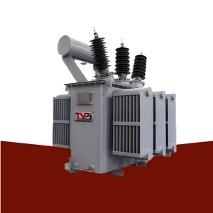
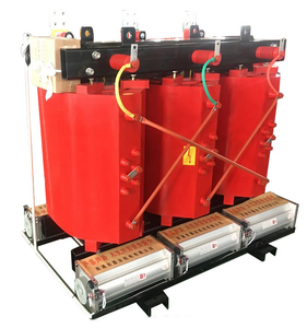
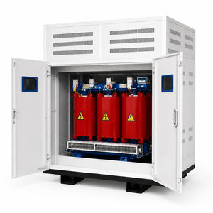
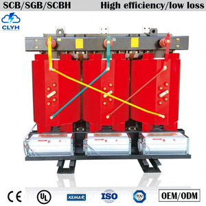
Unlike standard power distribution units operating under predictable sinusoidal loads, industrial furnace transformers function in the harshest electrical and thermal environments in modern manufacturing.
In Electric Arc Furnace (EAF) operations, scrap collapse events cause frequent dead short-circuits across secondary terminals. These rapid current spikes generate extreme electrodynamic radial and axial forces proportional to the square of the peak current ($I_{peak}^2$). Leading Chinese OEMs utilize continuous foil-winding technology coupled with high-density pressboard clamping rings and hydraulic core compression systems to resist mechanical displacement over millions of operational melt cycles.
Secondary currents in modern smelting furnaces frequently exceed 40,000 to 100,000 Amperes at low secondary voltages (100V to 1000V). Managing stray flux and preventing localized tank overheating demands interleaved copper busbar arrangements, non-magnetic stainless steel tank wall inserts, and integrated water-cooled secondary bushings (OFWF cooling). This prevents structural hotspot degradation and preserves dielectric integrity.
Furnace transformers require extremely wide voltage regulation steps (often up to 50% to 100% adjustment margin) to manage different operational phases—ranging from initial scrap bore-in to liquid bath refining. Top Chinese manufacturers integrate specialized multi-step OLTC systems with vacuum interrupters, reducing maintenance intervals from 50,000 operations to over 300,000 operations under heavy load switching.
Our manufacturing operations leverage vertically integrated processing to ensure every transformer delivers maximum efficiency, strict loss tolerances, and extended field service life.
Complete control over raw materials—utilizing top-tier Cold Rolled Grain Oriented (CRGO) silicon steel cut on automated step-lap slitting lines, coupled with dedicated tank fabrication, shot-blasting, and multi-layer anti-corrosion coating booths.
Eliminates transposition points inherent in traditional round-wire coils. Continuous copper/aluminium foil winding balances axial short-circuit forces, reduces hot-spot temperature rise, and maximizes dielectric heat dissipation under heavy harmonic loads.
Every unit undergoes 100% routine testing according to IEC 60076, IS 2026, and IS 1180 standards—including voltage ratio, vector group validation, winding resistance, insulation resistance, no-load loss ($P_0$), load loss ($P_k$), and impulse withstand tests.
As global heavy industries shift toward decarbonization and smart grid integration, industrial furnace transformer engineering is undergoing four critical technological transformations.
The global steel sector’s move toward Hydrogen Direct Reduced Iron (DRI) and scrap-based EAF production requires high-capacity step-down transformers equipped with advanced harmonic filtering. Modern Chinese exporters are supplying multi-winding step-down units tailored for direct integration with renewable hydrogen electrolyzer power units and static VAR compensators (SVCs).
To mitigate fire hazards inside indoor melt shops, buyers are increasingly replacing conventional mineral oils with biodegradable synthetic and natural ester dielectric liquids. Ester-filled furnace transformers feature higher fire points (>300°C), superior moisture absorption capabilities, and environmentally benign spill containment profiles.
Modern industrial buyers require real-time health diagnostics to prevent catastrophic plant downtime. Leading exporters now equip furnace transformers with integrated fiber-optic hotspot thermal sensors, continuous Dissolved Gas Analysis (DGA) monitors, and cloud-connected vibration monitoring modules for predictive maintenance asset management.
Procurement teams are shifting focus from initial capital expenditure (CAPEX) to 25-year Total Cost of Ownership models. By specifying ultra-low no-load ($P_0$) and load ($P_k$) losses adhering to EU Tier 2 Eco-design standards, plant operators save hundreds of thousands of dollars in lifetime operational energy costs.
Review indicative engineering parameters across major furnace transformer applications to guide your technical inquiry and RFP preparation.
| Furnace Application Type | Capacity Range (MVA) | Primary HV Voltage | Secondary LV Range | Cooling Mode | Voltage Regulation |
|---|---|---|---|---|---|
| Electric Arc Furnace (EAF) | 10 MVA - 160 MVA | 11kV / 33kV / 69kV / 110kV | 150V - 1200V (High Current) | ONAN / ONAF / OFWF | On-Load Tap Changer (OLTC) |
| Submerged Arc Furnace (SAF) | 5 MVA - 80 MVA | 11kV / 33kV / 66kV | 80V - 500V (Continuous Duty) | OFWF (Water Cooled) / ONAF | Motorized OLTC / De-energized |
| Ladle Refining Furnace (LRF) | 5 MVA - 40 MVA | 11kV / 33kV | 120V - 600V | ONAN / ONAF | Heavy-Duty OLTC |
| Induction Melting Furnace | 0.5 MVA - 15 MVA | 6.6kV / 11kV / 33kV | 380V - 1500V (Multi-Phase) | ONAN / Dry-Type Cast Resin | Off-Circuit Tap Changer (OCTC) |
| Electroslag Remelting (ESR) | 1 MVA - 25 MVA | 10kV / 35kV | 40V - 200V (Stepless LV) | OFWF / ONAN | Saturable Reactor / Thyristor |
Direct technical answers to common questions asked by global procurement directors, consultants, and EPC contractors.
Consult with our senior transformer application engineers to configure custom tap ranges, secondary current busbar connections, vector groups, and loss-optimized core designs for your plant requirements.
