Explore our certified transformer portfolio, precision-engineered to IS 1180, IS 2026, and IEC 60076 standards for severe industrial and utility grid environments.
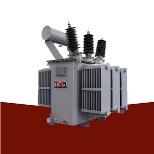
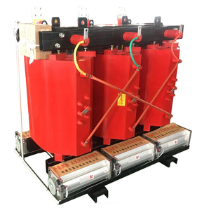
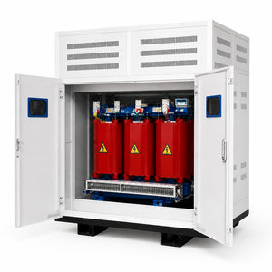
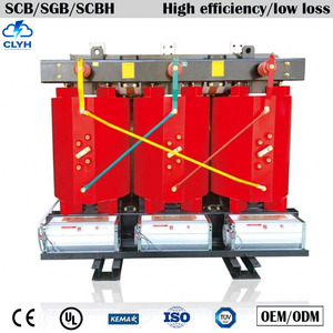
Global electrical grid modernization, coupled with the exponential expansion of utility-scale solar PV plants, offshore/onshore wind installations, hyper-scale data centers, and heavy industrial automation, has transformed the technical requirements for secondary power distribution. Modern procurement directors and EPC consultants no longer view substations as static, field-assembled civil structures. Instead, the market has rapidly pivoted toward pre-engineered, factory-tested Modular Substations (Compact Secondary Substations - CSS) and advanced transformer systems that dramatically compress deployment timelines, reduce civil overhead, and deliver guaranteed dielectric performance under harsh environmental stress.
“Information Gain Insight: Replacing traditional open-yard brick-and-mortar substations with factory-assembled Modular Secondary Substations reduces site installation footprints by up to 70%, cuts field labor hours by 85%, and eliminates ambient moisture contamination risks during critical core-coil assembly.”
As electrical grids transition toward decentralized renewable generation, transformers are subjected to dynamic thermal duty cycles and non-linear harmonic loading unheard of in legacy grid operations. Sourcing experts and electrical engineers must evaluate equipment based on four critical macro factors:
A critical engineering differentiator in modern distribution and power transformers is the transition from conventional round copper wire winding to Continuous Aluminium and Copper Foil Winding Technology for low-voltage coils. In traditional wire-wound transformers, electromagnetic axial short-circuit forces act unevenly across individual wire turns during external grid short circuits, often causing mechanical coil displacement, insulation abrasion, and ultimate catastrophic dielectric failure.
Foil winding technology utilizes full-width sheet conductor strips insulated by high-grade thermal films (Class F or Class H). Because each foil turn covers the full axial length of the coil, axial short-circuit forces are virtually eliminated. Mechanical stress is converted entirely into uniform radial forces, which the cylindrical core and coil structure resists with maximum rigidity. Furthermore, foil winding eliminates high-temperature localized hot-spots by providing an optimal surface-to-volume ratio for heat dissipation into mineral oil or cast resin channels, significantly extending transformer operating life.
From prime CRGO steel lamination cutting to rigorous high-voltage routine testing, our Rajkot facility executes end-to-end production under an ISO-certified quality management system.
Precision automated foil winding machines eliminate coil axial shift during short-circuit faults. Provides superior thermal withstand and lower hot-spot temperature rise across heavy load profiles.
Heavy-duty steel tank welding, shot blasting, and multi-stage polyurethane painting ensure IP55/IP65 weather sealing and salt-spray corrosion protection for severe outdoor environments.
Every transformer undergoes ratio, vector group, winding resistance, dielectric insulation resistance, separate-source voltage withstand, and full load/no-load loss testing prior to dispatch clearance.
Engineered with electrostatically shielded multi-windings to isolate grid transients from inverter IGBT bridges, suppressing high-frequency harmonics and voltage spikes.
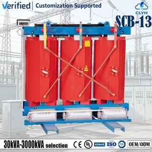
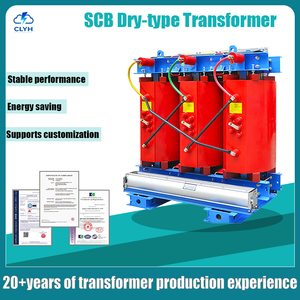
Flame-retardant, self-extinguishing epoxy resin encapsulation eliminates oil spill risks and maintenance overheads, offering safe indoor installation for medical facilities and commercial towers.
Factory-assembled modular kiosks housing MV Ring Main Units (RMU), power transformers, and LV distribution units designed in accordance with IEC 62271-202 safety standards.
Comprehensive comparative overview of standard product parameters for engineering consultants, EPC planners, and utility procurement officers.
| Equipment Category | Rating Envelope | Voltage Class | Cooling / Insulation | Core / Winding Architecture | Primary Standards |
|---|---|---|---|---|---|
| Compact Substation (CSS) | 250 kVA – 2500 kVA | 11 kV / 22 kV / 33 kV | ONAN Oil or Dry-Type Kiosk | Pre-wired MV VCB/RMU + LV Panel | IEC 62271-202 / IS 14728 |
| Substation Power Transformer | Up to 3500 kVA (30MVA custom) | Up to 33 kV / 69 kV | ONAN / ONAF Mineral Oil | High Permeability CRGO / Copper Foil | IEC 60076 / IS 2026 |
| Cast Resin Dry-Type Transformer | 100 kVA – 4500 kVA | Up to 33 kV class | Air Natural (AN) / Air Forced (AF) | Epoxy Cast F1/E2/C2 Class | IEC 60076-11 / IS 11171 |
| Solar / Wind Inverter Duty | 250 kVA – 3150 kVA | Up to 33 kV grid step-up | ONAN / Harmonics Rated Oil | Multi-Winding (3/4/5 Winding) | IEEE C57.158 / IEC 60076 |
| Induction Furnace Transformer | Custom Application Specific | Up to 33 kV Primary | ONAN / OFWF Heavy Duty | High Current Secondary Busbar | IEC 60076 Series |
| Distribution Transformer | 16 kVA – 3150 kVA | 11 kV / 22 kV / 33 kV | Hermetically Sealed / Conservator | Foil Winding Level 1/2 Loss Limits | IS 1180 / IS 2026 |
In-depth responses covering engineering compliance, custom design flexibility, witness testing protocols, and export logistics.
A Compact Secondary Substation (CSS) is a type-tested, factory-built enclosure containing a High-Voltage Switchgear (RMU/VCB), a Distribution Transformer (Oil-immersed or Cast Resin), and a Low-Voltage Switchboard. Unlike open-yard substations that require extensive civil foundations, cabling, and site assembly, a CSS operates as a single, tamper-proof, weather-sealed unit compliant with IEC 62271-202. It dramatically improves operator safety, reduces land footprint by up to 70%, and minimizes installation lead times.
Foil winding utilizes continuous sheet copper or aluminium across the full axial height of the coil. In traditional wire windings, short-circuit grid faults create severe axial forces that can displace wire turns and strip insulation. Foil winding transforms these destructive axial forces into uniform radial forces, giving the coil extraordinary short-circuit withstand capabilities. Additionally, foil eliminates internal air voids and hot-spots, ensuring uniform heat transfer and extended insulation life.
Solar Inverter Duty Transformers are custom-engineered to handle non-sinusoidal currents and high harmonic frequencies injected by solar PV inverters. They feature multi-winding secondary configurations (split LV windings) to accept inputs from multiple central inverters simultaneously without mutual interference. Furthermore, electrostatic shielding is placed between HV and LV coils to attenuate voltage surges and high-frequency noise, while thermal sizing accounts for K-factor harmonic heating.
Every unit manufactured in our facility undergoes a complete battery of routine tests in strict accordance with IEC 60076 and IS 2026. These tests include Voltage Ratio and Vector Group Verification, Winding Resistance measurement, Dielectric Insulation Resistance (Megger), Separate-Source AC Voltage Withstand, Induced Overvoltage Withstand, and No-Load / Load Loss Measurement. Customer witness testing or third-party inspection (SGS, TUV, Bureau Veritas, Intertek) is welcomed prior to seaworthy packing.
Standard IS 1180 distribution transformers (16 kVA to 1250 kVA) typically feature a production cycle of 3 to 5 weeks post drawing approval. Custom-designed power transformers (up to 33kV/69kV class), specialized furnace transformers, and fully integrated Compact Secondary Substations require approximately 6 to 10 weeks depending on custom switchgear integration, tap-changer specifications (OLTC vs. Off-Circuit), and raw material procurement schedules.
Consult with our senior technical sales team to request custom single-line diagrams (SLD), guaranteed technical particulars (GTP), drawing approvals, or competitive factory quotes.
