☉ Manufacturing since 2004 · Rajkot, Gujarat, India ✉ [email protected] ☎ +91 958 627 7766

Top Trusted Power Distribution Factories & Manufacturing Excellence

A Comprehensive Engineering & Procurement White Paper on Next-Generation Distribution Transformers, Grid Integration, and Industrial Manufacturing Standards

Flagship Transformer Solutions

Explore high-efficiency, standard-compliant oil-immersed and cast resin dry-type power distribution transformers engineered for extreme grid reliability.
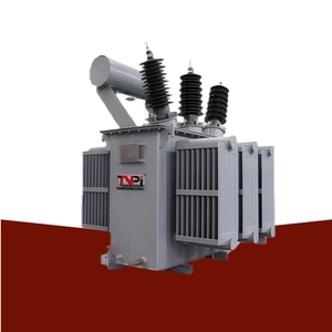
69kV 33kV 10MVA 20MVA 30MVA ONAN Copper Oil Immersed Power Transformer

69kV 33kV 10MVA 20MVA 30MVA ONAN Copper Oil Immersed Power Transformer for Substation Step Down

Primary Voltage: Up to 69kV / 33kV Capacity: 10MVA - 30MVA ONAN Conductor: 99.99% Electrolytic Copper
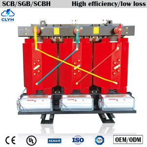
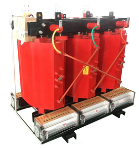
Cast Resin Dry Type Three Phase Power Distribution Transformer

Listed 11kv 13.2kv 0.4kv 1250kva 3150kva 4500kva Cast Resin Dry Type Three Phase Power Distribution Transformer

Voltage Class: 11kV / 13.2kV to 0.4kV Rating: 1250kVA - 4500kVA Insulation: Class H / Cast Resin
High Quality Dry Type Isolation Transformer 3 Phase Epoxy Resin Cast

50kva 250kva 400kva 500kva 630kva 380v 415v 480v High Quality Dry Type Isolation Transformer 3 Phase Epoxy Resin Cast CE

Ratings: 50kVA to 630kVA Secondary Voltage: 380V / 415V / 480V Certification: CE / IEC 60076
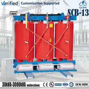
Low Loss SCB Series 315kva 10kv Epoxy Resin Cast Dry Type Transformer

Low Loss SCB Series 315kva 10kv Epoxy Resin Cast Dry Type 3 Phase Step Down Distribution Transformer

Series: SCB Low Loss Series Capacity: 315kVA / 10kV Step Down Feature: Flame Retardant / Low Noise
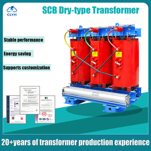
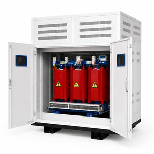
400kva 15KV Step Down Transformer 3 Phase Cast Resin Dry Type

400kva 15KV 0.4KV Step Down Transformer 3 Phase Cast Resin Dry Type for Industrial Power Supply & Data Centers

Application: Data Center & Heavy Industry Voltage: 15kV to 0.4kV Efficiency: High K-Factor Rated
High Efficiency IEC Standard 20KV 0.4KV 30KVA Dry Type Transformer

High Efficiency IEC Standard 20KV 0.4KV 30KVA Three Phase Cast Resin Dry Type Power Distribution Step Down Transformer

Standard: IEC 60076 / IS 2026 Voltage: 20kV to 0.4kV Rating: 30kVA Compact Footprint
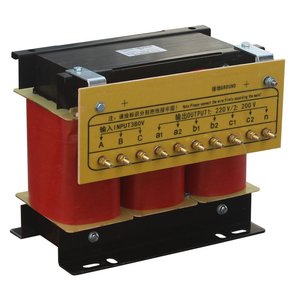
3 Phase Dry Type Isolation Transformer Low Voltage Medical Grade

3 Phase Dry Type Isolation Transformer 100kva 400kva Low Voltage for Industrial Equipment Medical Grade

Grade: Industrial & Medical Grade Range: 100kVA - 400kVA Low Voltage Harmonic Suppression: Electrostatic Shielding
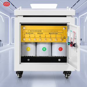
High Quality Dry Type 220v 380v Transformer 50kva AC Isolation

High Quality Dry Type 220v 380v Transformer 50kva 25kva 15kva 3 Phase AC Isolation Transformer Power Transformer

Secondary Output: 220V / 380V AC Capacity Options: 15kVA, 25kVA, 50kVA Cooling: Natural Air (AN) / Forced Air
103,500+
Sq. Ft. Plant Facility
3,000+
Global Grid Deployments
100%
Routine & FAT Tested
<0.1%
Field Failure Rate

Industrial Engineering & Manufacturing Excellence

A transparent look inside world-class transformer manufacturing processes, metallurgical standards, and strict quality assurance protocols.

In electrical power infrastructure, the reliability of a power distribution transformer dictates the operational security of entire utility networks, industrial complexes, and commercial data facilities. Modern power factories must merge advanced electromagnetic physics with precision manufacturing to deliver units capable of surviving continuous thermal stress, harmonic distortions, and severe short-circuit electromagnetic forces.

Key Engineering Benchmark: Authentic manufacturing authority is verified not merely by factory size, but by in-house core cutting, automated foil winding, vacuum pressure impregnation (VPI), state-of-the-art oil filtration equipment, and NABL/IEC-accredited routine testing bays.

1. Advanced Core Metallurgy & CRGO Processing

The magnetic core forms the heart of any power transformer. Top-tier factories exclusively utilize Cold-Rolled Grain-Oriented (CRGO) silicon steel (such as M0H, M1H, or laser-scribed domain-refined grades) imported directly from tier-1 steel mills. Core fabrication follows strict engineering guidelines:

  • Step-Lap Mitred Joints: 45-degree precision step-lap cutting minimizes flux density distortion at corners, significantly reducing no-load losses (hysteresis and eddy current losses) and acoustic noise emissions.
  • Burr-Free Shearing: CNC cutting lines ensure burr heights remain strictly under 0.02 mm, preventing inter-laminar short circuits and minimizing core hot spots.
  • Rigid Core Clamping: Heavy-duty steel structural channels and tie rods apply uniform mechanical pressure, maintaining structural integrity against seismic activity and transient fault currents.

2. Foil & Wire Winding Topology

Mechanical withstand capability during short-circuit events is largely governed by winding geometry and material purity. Leading factories implement automated foil-winding machine technology for low-voltage (LV) coils alongside wire-wound high-voltage (HV) layers:

  • Foil Winding Advantage: Using continuous copper or aluminum sheet foil eliminates axial short-circuit forces. In conventional round wire windings, axial forces can push coils apart during external short circuits; foil winding completely balances these axial magnetic forces.
  • Thermal Dissipation Channels: Duct spacers are woven into high-voltage layers, facilitating uniform oil flow (in ONAN/ONAF units) or natural air convection (in Cast Resin Dry-Type units), eliminating localized thermal hot spots.
  • High-Dielectric Insulation: Thermally upgraded Kraft paper, Nomex®, and high-grade epoxy resin systems guarantee insulation longevity rated for Class F (155°C) or Class H (180°C) temperature rises.

Automated Core & Coil Assembly

Robotic winding and precise hydraulic core clamping minimize human error, guaranteeing tight tolerance matching against electrical design sheets.

Vacuum Pressure Impregnation

Deep vacuum resin impregnation removes all trapped micro-bubbles, ensuring partial discharge levels remain under 10 pico-coulombs (pC).

Hermetically Sealed Enclosures

Corrosion-resistant steel tanks undergo shot-blasting, multi-layer epoxy powder coating, and helium leak testing for lifetime oil containment.

Technical Specification & Application Benchmark Matrix

A side-by-side engineering comparison designed to aid EPC procurement managers and utility engineers in selecting the optimal transformer architecture.

Specification Parameter Oil-Immersed Power Transformer Cast Resin Dry-Type (CRT) Low-Voltage Isolation Unit Solar/Wind Inverter Duty
Standard Voltage Class 11kV, 22kV, 33kV, up to 69kV 11kV, 13.2kV, 20kV, 33kV 110V, 220V, 380V, 415V, 480V 11kV to 33kV (Grid Side)
Power Rating Range 100 kVA to 30 MVA 100 kVA to 4,500 kVA 15 kVA to 630 kVA 250 kVA to 3,150 kVA
Cooling Medium / Type Mineral Oil / Synthetic Ester (ONAN/ONAF) Natural Air / Forced Air (AN/AF) Dry Air Natural Convection Oil-Immersed / Dry-Type Option
Fire Safety Rating Standard (Requires oil pit/firewall) F1 Class (Self-extinguishing) High (Indoor Safe) High Thermal Tolerance
Harmonic Tolerance Standard (K-Factor 1 to 4) High (K-Factor up to K-13/K-20) Electrostatic Shielded (K-13) Extreme (Multi-Winding Inverter)
Primary Application Substations, Heavy Utility Feeder High-Rise Malls, Hospitals, Data Centers Sensitive Medical & CNC Machinery Solar PV Plants & Wind Turbines
Standard Compliance IEC 60076, IS 2026, IS 1180 Level 1/2 IEC 60076-11, IEEE C57.12.01 CE, IEC 61558-2-4 IEC 60076, Grid Code Compliant

Strategic B2B Procurement & Evaluation Framework

Essential methodology for calculating Total Cost of Ownership (TCO), capital expenditure vs operational expenditure, and factory audit criteria.

When evaluating bids from global power distribution factories, looking solely at the upfront purchase price (CAPEX) can result in long-term financial losses. Losses occurring inside the transformer core and conductor windings generate heat that must be paid for every hour the unit remains energized over its typical 25 to 30-year operational lifespan.

1. Total Cost of Ownership (TCO) Calculation Formula

Leading energy consultants and utility buyers compute TCO using capitalized loss formulas tailored to local electricity tariff structures:

TCO Formula: TCO = CAPEX + (A × No-Load Loss in kW) + (B × Load Loss in kW)
Where:
• CAPEX: Delivered cost of transformer and switchgear installation.
• A (Capitalization Factor for No-Load Loss): Typically ranges from $4,000 to $9,000 per kW, reflecting continuous 24/7 core loss.
• B (Capitalization Factor for Load Loss): Typically ranges from $1,500 to $3,500 per kW, reflecting loading profile square law losses.

By specifying high-efficiency designs (such as BIS 1180 Level 2 or EU Tier 2 Eco-design standard compliant units), the higher initial purchase price is often fully recouped within 24 to 36 months through substantial utility bill savings.

2. Vendor Qualification & On-Site Factory Audit Checklist

Before issuing a Purchase Order (PO) to any international distribution transformer factory, technical procurement directors should audit the following key capabilities:

  • Raw Material Traceability: Ensure Mill Test Certificates (MTC) are available for all batch runs of CRGO steel coils, electrolytic copper rods, and transformer insulating oil.
  • Routine Test Equipment Calibration: Verify that the factory's impulse generator, power frequency voltage test bench, precision power analyzer, and oil breakdown voltage (BDV) testers possess current ISO/IEC 17025 calibration seals.
  • Tank Pressure & Leak Testing: Confirm tanks undergo positive pressure oil leak testing and vacuum withstand tests to prevent oil seepage during field operation.
  • Winding Cleanroom Environment: Dust particles settling on high-voltage windings cause insulation degradation. High-voltage winding bays must operate in positive-pressure, dust-controlled spaces.

Future Procurement Trends in Power Distribution (2025–2035)

How grid decarbonization, renewable power integration, and smart monitoring are redefining transformer manufacturing requirements worldwide.

The global distribution transformer ecosystem is undergoing a dramatic shift driven by the transition toward renewable energy, electric vehicle charging infrastructure, and localized microgrids. Procurement executives must align their technical specifications with upcoming technological trends:

1. Transition to Biodegradable Synthetic & Natural Esters

Traditional mineral oil is rapidly being replaced by synthetic and natural ester dielectric fluids (such as FR3®). Ester fluids offer a fire point exceeding 300°C (K-class rating), rendering them virtually non-flammable. Furthermore, natural esters are 100% biodegradable within 28 days, preventing catastrophic soil contamination in environmentally sensitive zones.

2. IoT-Enabled Smart Transformers & Real-Time Health Indexing

Modern distribution substations are evolving from static assets to intelligent nodes. Advanced factories are embedding digital sensor suites directly into transformer tanks during assembly:

  • Fiber-Optic Hotspot Sensing: Monitors internal coil temperatures directly at the conductor level rather than relying on top-oil estimates.
  • Online Dissolved Gas Analysis (DGA): Detects hydrogen, methane, and acetylene gas generation in real time, alerting maintenance teams to arcing or thermal breakdown before catastrophic failure occurs.
  • Smart Bushings & Vibration Monitoring: Tracks dielectric tan-delta insulation decay and core clamping stress shifts via acoustic signatures.

3. Hybrid Multi-Winding Solar & Energy Storage Coupling

With utility-scale solar PV and Battery Energy Storage Systems (BESS) taking center stage, distribution transformers must handle bidirectional power flow and severe harmonic distortion caused by high-frequency inverter switching. Dual-LV and Quad-LV secondary winding configurations allow multiple inverter banks to connect to a single step-up transformer, drastically lowering balance-of-plant (BOP) capital costs.

Frequently Asked Questions (FAQ)

Detailed technical and commercial answers addressing common inquiries from overseas EPC contractors, utility buyers, and industrial engineers.

Q1: Which electrical standards and certifications govern your distribution transformer manufacturing?
Our transformers are custom-engineered, manufactured, and tested in strict compliance with major international standards, including IEC 60076 (Power Transformers), IS 2026, IS 1180 (Energy Efficiency Levels 1 & 2), IEEE C57.12.00, and ANSI standards. Cast resin dry-type transformers conform to IEC 60076-11 with environmental, climatic, and fire behaviour classes F1, E2, C2. CE and ISO 9001:2015 certifications accompany every dispatch dossier.
Q2: Why is foil winding preferred over traditional round wire winding for distribution transformers?
Foil winding utilizes continuous copper or aluminum sheet metal for low-voltage windings instead of multiple strands of round or rectangular wire. This design completely eliminates axial short-circuit forces by distributing electrical stress evenly across the full height of the coil. Additionally, foil winding substantially improves heat dissipation surface area, lowers localized hot-spot temperature rise, and guarantees superior resistance against heavy electrical short-circuit grid faults.
Q3: What is the typical lead time for custom distribution transformers and substation packages?
Standard distribution transformer ratings (such as 100kVA to 2500kVA units with standard voltage ratios) typically carry a lead time of 3 to 5 weeks following GA drawing approval. Highly customized power transformers, multi-winding solar inverter transformers, or compact secondary substations (CSS) requiring special On-Load Tap Changers (OLTC) or specialized enclosures generally require 6 to 10 weeks depending on raw material sourcing and factory test bay scheduling.
Q4: Can client engineers or third-party inspection agencies (TPIA) witness routine and type testing?
Absolute transparency is fundamental to our quality ethos. We warmly welcome client witness testing as well as third-party inspection agencies (such as Bureau Veritas, SGS, TUV, Intertek, or Lloyd's Register) at our factory test bay in Rajkot, India. Complete routine test procedures—including winding resistance, voltage ratio, vector group verification, short-circuit impedance, no-load/load loss measurement, separate-source voltage withstand, and induced overvoltage tests—are performed before dispatch clearance.
Q5: How do you ensure seaworthy export packaging and prevent moisture ingress during shipping?
All export-bound units undergo heavy-duty tropicalization. Oil-immersed units are shipped completely filled with processed transformer oil or under positive dry nitrogen gas pressure (with tank pressure gauges monitored throughout transit). Tanks are secured inside reinforced wooden crates or flat-rack containers with heavy-duty structural lashing, anti-vibration rubber pads, and vacuum-sealed moisture-barrier foil wrap to withstand ocean moisture, shock, and salt air exposure.
Q6: What is the difference between On-Load Tap Changer (OLTC) and Off-Circuit Tap Changer (OCTC)?
An Off-Circuit Tap Changer (OCTC) requires the transformer to be completely de-energized (isolated from the electrical grid) before manually shifting voltage tap ratios. It is suitable for networks with stable supply where seasonal adjustment suffices. An On-Load Tap Changer (OLTC) contains complex high-speed diverter switches that adjust voltage winding ratios automatically while the transformer remains energized and under load, maintaining stable output voltage despite volatile primary grid fluctuations.
Q7: What after-sales installation, oil filtration, and spare parts support do you provide globally?
We maintain a dedicated field service team that provides site commissioning supervision, oil filtration assistance, transformer bushing replacement, gasket maintenance, and tap-changer calibration. Furthermore, every shipped unit includes complete spare part support kits (including spare gaskets, oil sight glasses, Buchholz relays, temperature indicators, and explosion vents) to ensure smooth maintenance operations throughout the transformer lifecycle.