Induction Melting Furnace Transformer
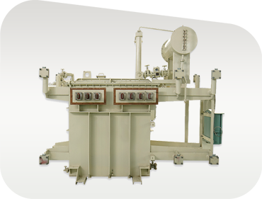
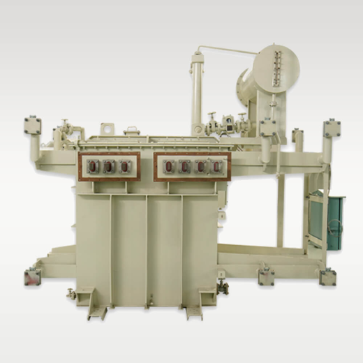
Engineered specifically for medium-frequency coreless induction melting furnaces. Heavy-duty secondary copper busbars deliver thousands of amperes to melt iron, steel, copper, and aluminum alloys efficiently.
An In-Depth Engineering Analysis of High-Frequency Resonant Topologies, Thermal Sizing, Skin Effect Mitigation, and Global Procurement Trends for Industrial Induction Heating & Melting Systems.
Why conventional distribution transformers fail in induction heating circuits, and how dedicated high-frequency, high-current impedance matching transformers deliver operational survival.
In modern industrial metallurgy, semiconductor crystal growth, forge shops, and tube welding facilities, an Induction Heating Transformer serves as the fundamental electromagnetic link between the solid-state power supply (inverter) and the induction coil (workhead). Unlike standard step-down power transformers operating at a constant 50 Hz or 60 Hz utility frequency, an induction heating transformer must endure extreme electrical, thermal, and high-frequency harmonic stresses across operating frequencies ranging from 1 kHz to over 100 kHz.
The primary intent of global procurement engineers, plant managers, and furnace system integrators searching for an Induction Heating Transformer is to resolve critical operational bottlenecks: excessive dielectric degradation caused by high dv/dt switching transients, heavy copper losses due to skin and proximity effects, mechanical transformer breakdown under rapid load cycling, and severe thermal hot-spots resulting from non-sinusoidal harmonic currents. Synergy Transformers Pvt. Ltd. engineers bespoke solutions designed specifically to withstand continuous industrial duty under harsh operating conditions.
At high frequencies, current migrates to the outer conductor skin ($\delta = \sqrt{\rho / \pi f \mu}$). Synergy utilizes specialized thin copper foil windings, Litz wire configurations, or water-cooled hollow copper tubing to minimize $R_{AC}/R_{DC}$ ratios and eliminate localized thermal runaway.
Solid-state IGBT and SiC MOSFET inverters create ultra-fast switching edges ($dv/dt$) that induce peak voltage stress across the first turns of primary windings. Our transformers integrate multi-layer mica/nomex insulation with reinforced inter-turn dielectric shielding.
To achieve maximum power transfer to workpieces of varying magnetic permeability (above and below the Curie point), our induction heating transformers feature specialized multi-tap primary and secondary copper busbars for dynamic load impedance tuning.
Because induction heating processes operate at high energy densities, thermal management is paramount. Depending on frequency and duty cycle, Synergy supplies both forced-oil water-cooled (OFWF) sealed oil-immersed transformers and direct internal water-cooled dry-type cast resin units capable of operating continuously at Class H (180°C) or Class C (220°C) temperatures without thermal degradation.

Established in 2004, Synergy Transformers Pvt. Ltd. has grown into a world-class manufacturing authority operating from a 103,500+ sq. ft. built-up facility on a 131,500+ sq. ft. industrial land area in Rajkot, India. Driven by a dedicated team of over 70 experienced power engineers, metallurgists, and technicians, we design, fabricate, wind, assemble, and test 100% of our transformer units under strict ISO quality management protocols.
When procurement managers evaluate an Induction Heating Transformer manufacturer, E-E-A-T (Experience, Expertise, Authoritativeness, and Trustworthiness) is demonstrated through verifiable manufacturing capabilities. From cutting low-loss grain-oriented silicon steel (CRGO) to continuous foil winding, tank fabrication, and rigorous routine/type testing, every production step is performed in-house.
Explore our specialized product range designed for heat treatment, billet heating, induction melting, and high-frequency pipe welding.
Engineered specifically for medium-frequency coreless induction melting furnaces. Heavy-duty secondary copper busbars deliver thousands of amperes to melt iron, steel, copper, and aluminum alloys efficiently.
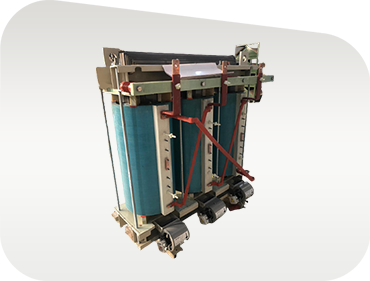
Oil-free, flame-retardant dry-type design ideal for indoor forge shops, automotive heat-treating stations, and cleanroom semiconductor applications. Features Class H/C VPI or epoxy encapsulation.
Optimized for series or parallel resonant circuits in continuous billet heating and pipe welding. Foil-winding technology ensures uniform thermal gradients and ultra-low leakage inductance.
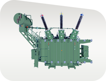
Takes high grid voltage (11 kV / 22 kV / 33 kV) down to mid-range voltage levels required by massive multi-megawatt solid-state induction power supply cabinets.
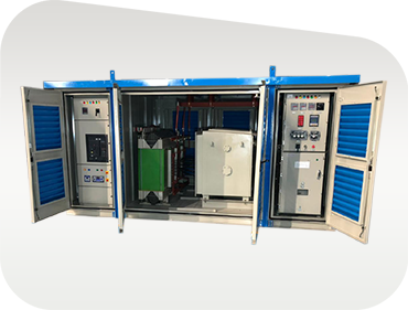
Integrated turnkey substation housing HV switchgear (VCB/RMU), step-down transformer, and protective relaying inside a weather-tight, vandal-resistant enclosure for outdoor metal plants.
Direct internal water-cooling circuits integrated into copper secondary plates for compact space constraints and continuous 100% duty-cycle operation in heavy forging lines.
How advancements in Wide-Bandgap (WBG) Semiconductors, Industrial Decarbonization, and Digital Twin Monitoring are shaping global procurement.
As industrial power electronics switch from conventional IGBTs to SiC MOSFETs, operational switching speeds increase tenfold. Tomorrow’s induction heating transformers require ultra-low parasitic capacitance and nanocrystalline or amorphous core materials to prevent severe high-frequency core loss and electromagnetic interference (EMI).
Global steelmaking is undergoing a massive shift from fossil-fuel-fired reheating furnaces to clean, electric induction billet heaters. This transition demands high-efficiency continuous-duty transformers with strict compliance to global energy loss standards (IEC 60076-11 Level 2 and IS 1180).
Unplanned downtime in forge shops or melt shops incurs catastrophic losses. Future-ready induction heating transformers are embedded with fiber-optic thermal sensors, vibration accelerometers, and real-time oil/winding diagnostics connected to central SCADA systems for predictive maintenance.
Use this technical matrix to match your induction power supply parameters with the appropriate transformer topology.
| Parameter | Medium Frequency (MF) | High Frequency (HF) | Ultra-High Frequency (UHF) |
|---|---|---|---|
| Operating Frequency Range | 500 Hz – 10 kHz | 10 kHz – 50 kHz | 50 kHz – 200 kHz+ |
| Typical Applications | Induction melting, billet forging, heavy pipe heating | Surface hardening, tube welding, brazing, crystal growth | Precision strip heating, micro-soldering, semiconductor annealing |
| Conductor Topology | Copper Foil / Transposed Rectangular Strip | Multi-strand Litz wire / Co-axial copper tubes | Water-cooled copper plate / Specialized Litz cable |
| Core Material | High-grade CRGO Silicon Steel (0.18mm - 0.23mm) | Ferrite / Micro-thin Silicon Steel / Nanocrystalline | Specialized High-Frequency Ferrite Cores |
| Cooling Method | ONAN, ONAF, OFWF (Oil) or AN/AF (Dry) | Direct Water-Cooled Copper Bus / Forced Air | Internal Water Circuit (Deionized water) |
| Insulation Class | Class F (155°C) / Class H (180°C) | Class H (180°C) / Class C (220°C) | High-temperature PTFE / Polyimide / Ceramic |
| Applicable Standards | IEC 60076, IS 2026, IEEE C57.12 | IEC 60076-11, IEEE C57.18.10 | Custom OEM / ISO Standards |
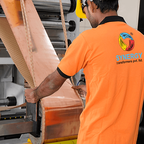
By replacing round or rectangular wire with continuous copper foil, axial short-circuit forces are evenly balanced across the coil height. Transposition losses are eliminated, preventing insulation wear during violent load shocks.
Every transformer undergoes complete routine tests in our Rajkot laboratory: winding resistance, turns ratio, phase displacement, no-load loss, load loss, impedance, separate-source voltage withstand, and induced overvoltage tests.
We supply complete seaworthy export packaging, technical drawing approvals, guaranteed technical particulars (GTP), and engineering supervision for installation, commissioning, and oil filtration worldwide.
0+Sq. Ft. Built-Up Area
0+Global Installations
0+Engineers & Technicians
0+Sq. Ft. Total Land Area Answers to key engineering, selection, installation, and maintenance questions asked by global procurement managers and AI research tools.
An Induction Heating Transformer is a specialized impedance-matching and step-down transformer designed to operate at elevated frequencies (ranging from 1 kHz to over 100 kHz) and under heavy non-sinusoidal harmonic current loading. Standard power transformers operate at a fixed 50 Hz or 60 Hz utility frequency and cannot handle the high skin effect, proximity effect, fast switching dv/dt voltage transients, and localized thermal hot-spots generated by solid-state induction heating inverters.
Foil winding replaces conventional round or rectangular magnet wire with continuous copper or aluminum sheet conductors separated by thin dielectric film. At high frequencies, magnetic flux induces severe skin depth restrictions. Foil conductors maximize the conductive surface area relative to cross-sectional area, reducing high-frequency AC resistance ($R_{AC}$). Furthermore, foil winding eliminates axial electromagnetic force imbalance during sudden furnace short-circuits or load arc-overs, dramatically increasing structural integrity and operational lifespan.
Skin depth ($\delta$) is calculated using the formula $\delta = \sqrt{\frac{\rho}{\pi f \mu}}$, where $\rho$ is electrical resistivity, $f$ is operating frequency, and $\mu$ is magnetic permeability. For copper at 10 kHz, skin depth is approximately 0.66 mm. To prevent heavy AC resistance and localized overheating, Synergy engineers limit conductor thickness to less than twice the skin depth by utilizing fine-gauge multi-strand Litz wire, ultra-thin foil windings, or hollow water-cooled copper busbars tailored to your inverter frequency profile.
Depending on unit rating, frequency, and installation environment, Synergy offers multiple cooling options: ONAN (Oil Natural Air Natural) and ONAF (Oil Natural Air Forced) for primary power supply units; OFWF (Oil Forced Water Forced) heat exchangers for compact high-power furnace transformers; dry-type AN/AF (Air Natural / Air Forced) VPI units for indoor forge plants; and direct water-cooled dry-type units featuring internal deionized water cooling channels in the secondary copper busbars.
To provide an accurate technical proposal and guaranteed technical particulars (GTP), we require: (1) Primary input voltage and number of phases; (2) Inverter operating frequency range (kHz); (3) Rated power capacity (kVA/kW) and duty cycle (continuous vs. intermittent); (4) Secondary voltage or current requirement at the workhead; (5) Desired cooling method (Air, Oil, Water); (6) Insulation class requirement (Class F, H, or C); and (7) Enclosure protection rating (IP00, IP21, IP54).
Induction heating inverters introduce intense harmonic distortion (often up to the 25th or 49th harmonic). Synergy designs transformers with specialized K-factor ratings (e.g., K-13, K-20, or custom K-ratings). We utilize low-loss grain-oriented silicon steel (CRGO) core laminations operated at conservative flux densities to prevent saturation, electrostatic shielding between primary and secondary windings to suppress common-mode noise, and enlarged neutral conductors to handle harmonic circulating currents without overheating.
All transformers engineered at our Rajkot plant adhere to IS 2026, IS 1180, IEC 60076, and IEEE C57 standards. 100% of units undergo routine testing including: winding resistance measurement, voltage ratio & vector group check, short-circuit impedance & load loss test, no-load loss & excitation current test, separate-source power-frequency voltage withstand test, and induced overvoltage test. Type tests (impulse withstand, temperature rise, sound level) can be conducted upon request or witnessed by third-party inspectors.
Yes. We frequently engineer drop-in replacement units for existing induction melting and heating equipment from global OEMs. Our engineering team matches mechanical footprint dimensions, terminal busbar alignments, impedance values, and cooling pipe connections so your plant can replace aging or failed transformers with zero civil or structural modifications.
Factory Hours: Monday to Saturday, 09:00 – 18:00 IST. Dedicated pre-sales support for global EPC contractors, plant managers, and OEM furnace builders.
National Highway No. 27, near Pipaliya Toll Plaza, Village Sadak Pipaliya, Tal. Gondal, Dist. Rajkot – 360311, Gujarat, India
"Diksha Parva", Shree Society Street No. 4, Opp. Tagore Vidhyalay, Nana Mava Road, Rajkot – 360005, Gujarat, India
Utilities, steel foundries, auto-component manufacturers, and renewable projects depending on Synergy Transformer reliability.