☉ Manufacturing since 2004 · Rajkot, Gujarat, India ✉ [email protected] ☎ +91 958 627 7766
Engineering & Procurement Master Guide

Industrial Power Distribution Transformer: Sizing, Technical Standards & Intent-Driven Procurement Blueprint

An authoritative technical guide for global electrical engineers, EPC contractors, utility planners, and procurement directors. Sizing methodologies, IEC 60076 & IS 1180 compliance, advanced foil winding mechanics, future industry trends, and verified product specifications from Synergy Transformers Pvt. Ltd.

Rating Envelope: 16 kVA to 3500 kVA Voltage Class: Up to 33 kV Standards: IEC 60076 / IS 1180 / IS 2026 Manufacturing: Rajkot, Gujarat, India (Est. 2004)
Inquire Now
Technical Deep Dive

Understanding the Industrial Power Distribution Transformer

An Industrial Power Distribution Transformer is the critical backbone of industrial power infrastructure. It steps down medium-voltage (MV) utility transmission levels—typically 11 kV, 22 kV, or 33 kV—to low-voltage (LV) operational levels (such as 415V, 433V, 480V, or 690V) suitable for heavy industrial machinery, plant drives, arc furnaces, motor control centers (MCCs), and facility distribution networks. Unlike standard commercial transformers, industrial distribution units must operate continuously under non-linear loads, aggressive thermal cycling, harmonic distortion from variable frequency drives (VFDs), and harsh environmental ambient conditions.

When global procurement teams search for an Industrial Power Distribution Transformer, their intent extends far beyond basic nameplate kVA ratings. Search quality expectations require clear technical transparency regarding electrical losses, thermal class limits, magnetic flux density, short-circuit withstand capabilities, and international standard compliance. Sizing an industrial unit requires evaluating continuous load current, peak surge current during large motor starting, transformer impedance (%Z) to limit fault levels on downstream switchgear, and vector group selection (e.g., Dyn11 or Dyn5) for proper neutral grounding and harmonic attenuation.

Key Architectural Components of Modern Industrial Transformers

Every high-reliability distribution transformer manufactured by Synergy Transformers incorporates precision-engineered active and passive components engineered for a 25-to-30-year operational design life:

  • Magnetic Core Assembly: Constructed from high-permeability, cold-rolled grain-oriented (CRGO) silicon steel laminations (M4, ZH, or domain-refined grades). Precision step-lap mitered joints minimize magnetic reluctance, stray flux, no-load losses (P0), and acoustic noise emissions.
  • Primary & Secondary Windings: Engineered using electrolytic high-conductivity copper or EC-grade aluminium. Secondary windings feature continuous foil winding technology to eliminate axial short-circuit displacement forces.
  • Solid & Liquid Insulation Systems: Thermally upgraded kraft paper, high-density pressboard, and Class A, F, or H insulation materials combined with refined naphthenic mineral oil (IEC 60296) or high-fire-point synthetic ester fluids.
  • Tank Construction & Protection Suite: Heavy-gauge structural steel tanks with corrugated fin radiators or detached radiator banks, treated with 7-tank chemical pre-treatment and polyurethane powder coating. Fitted with Buchholz relays, magnetic oil level gauges (MOG), oil temperature indicators (OTI), winding temperature indicators (WTI), pressure relief devices (PRD), and silica gel breathers.
Verified Product Range

Industrial Power Distribution Transformer Recommendations

Six customized product architectures designed for utility grids, manufacturing facilities, renewable energy integration, and extreme duty applications.

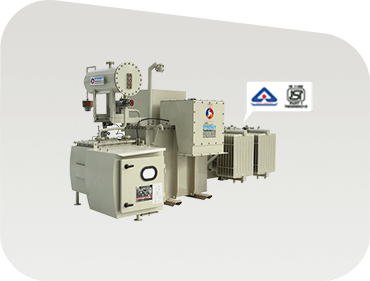
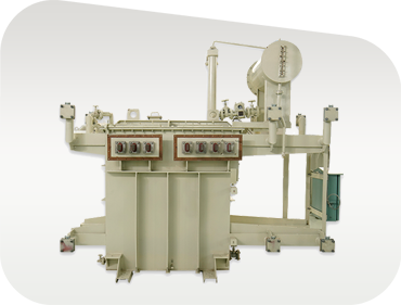
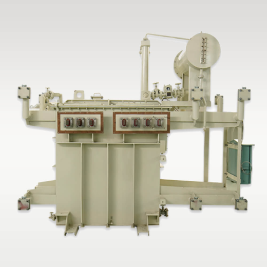
Oil Immersed Industrial Power Distribution Transformer manufactured by Synergy Transformers

Oil-Immersed Distribution Transformers

Engineered for factory distribution sub-stations and utility networks. Features foil-wound secondary coils, hermetically sealed or conservator designs, low loss CRGO core, and compliance with IS 1180 Level 1 / Level 2 and IEC 60076 standards.

16 kVA – 3150 kVA11 / 22 / 33 kV ClassONAN Cooling
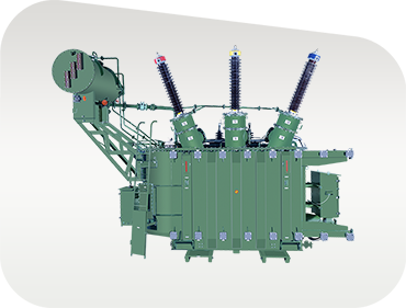
Industrial Power Step Up Transformer for substation tie ins

Industrial Power Transformers

Step-up and step-down power transformers designed for major sub-station tie-ins, heavy continuous process plants, and mining complexes. Available with On-Load Tap Changers (OLTC) or Off-Circuit Tap Changers (OCTC).

Up to 3500 kVAUp to 33 kVONAN / ONAF
Solar and Wind Renewable Inverter Duty Transformer

Solar / Wind Inverter Duty Transformers

Multi-winding step-up transformers designed to handle high harmonic spectra, K-factor loading, and daily solar/wind thermal cycling. Integrates electrostatic shielding between windings to prevent HF transient transfer.

Multi-Winding LVHarmonic RatedGrid Step-Up
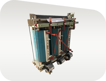
Cast Resin Dry Type Transformer for indoor facility installation

Cast Resin Dry-Type (CRT) Transformers

Oil-free, flame-retardant, self-extinguishing cast resin transformers for high-rise buildings, commercial centers, indoor industrial substations, and cleanroom environments. Certified to F1 fire, E2 environmental, C2 climatic classes.

100 – 2500 kVAF1 / E2 / C2 ClassZero Oil Risk
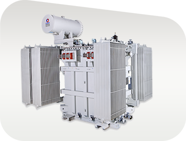
Heavy Duty Induction Melting Furnace Transformer

Induction Melting Furnace Transformers

Purpose-engineered for steel plants, foundries, and metallurgical refining. Built with reinforced mechanical clamping, heavy copper busbars for high LV current outputs, and extreme thermal overload capabilities.

High Current LVHeavy Mechanical DutyThermal Shock Proof
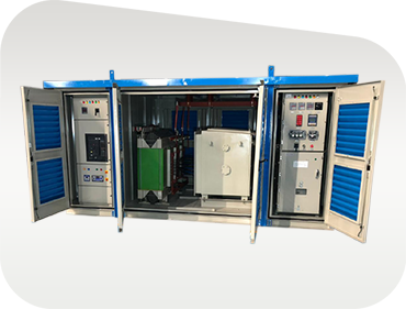
Compact Secondary Substation CSS with VCB RMU and Transformer

Compact Secondary Substations (CSS)

Factory-assembled, weather-proof kiosk substations integrating HT switchgear (VCB/RMU), distribution transformer, and LT distribution panel inside a single vandal-resistant enclosure compliant with IEC 62271-202.

Integrated KioskVCB / RMU SwitchgearPlug & Play
Manufacturing Excellence

Why Global Procurement Teams Choose Synergy Transformers

Over two decades of precision transformer engineering from Rajkot, Gujarat, India. Built with complete in-house control over every step of core assembly, winding, tank fabrication, and testing.

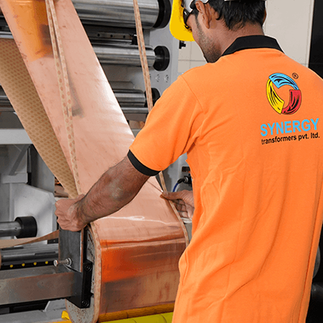
Advanced Foil Winding Machine in Synergy plant

Foil Winding Technology

Our dedicated foil winding machinery ensures precise tension control, edge-burr removal, and automated layer insulation placement, delivering unmatched short-circuit withstand capabilities and lower thermal hot-spot gradients.

CRGO core stack and active part assembly

Energy Loss Optimisation

We manufacture transformers engineered strictly to IS 1180 Level 1 / Level 2 energy efficiency standards and IEC 60076 loss limits. High-grade CRGO laminations ensure guaranteed no-load and load loss values on every nameplate.

In-house high voltage testing laboratory at Synergy

In-House Testing Bay & Traceability

Every single unit undergoes complete routine testing in our state-of-the-art laboratory before dispatch. Routine test reports, mill test certificates for CRGO and oil, and full batch component traceability are supplied with every order.

Quantifiable Infrastructure

Auditable Manufacturing Capacity

Built up plant area icon 103,500+Sq. Ft. Built-Up Factory Area
Global client icon 3,000+Global Installations Worldwide
Engineering team icon 70+Experienced Engineers & Technicians
Land footprint icon 131,500+Sq. Ft. Total Land Area
Technical Reference

Industrial Distribution Transformer Selection Matrix

Review standard design parameters across core product lines for initial RFP drafting and engineering selection.

Comprehensive engineering parameters for Synergy Industrial Transformers. Custom vector groups, special voltage taps, and tropicalized designs available upon request.
Product Architecture Rating Range (kVA) Primary Voltage Class Secondary Voltage Cooling / Insulation Applicable Standards
Oil-Immersed Distribution 16 – 3150 kVA 11 / 22 / 33 kV 415V / 433V / 11kV ONAN / Mineral Oil or Ester IS 1180, IS 2026, IEC 60076
Industrial Power Step-Down Up to 3500 kVA Up to 33 kV 3.3kV / 6.6kV / 11kV ONAN / ONAF IEC 60076-1, IS 2026
Cast Resin Dry-Type (CRT) 100 – 2500 kVA 11 / 22 / 33 kV 415V / 433V AN / AF (Air Cooled) IEC 60076-11, IS 11171
Solar / Wind Inverter Duty 250 – 3150 kVA 11 / 22 / 33 kV 600V / 690V / 800V ONAN (Multi-Winding) IEC 60076-16, IS 2026
Induction Furnace Transformer Custom Ratings 11 / 22 / 33 kV High Current Low Voltage ONAN / OFWF IEC 60076 Series
Compact Substation (CSS) 250 – 2500 kVA 11 / 22 / 33 kV 415V / 433V Enclosed Kiosk IEC 62271-202

100% Quality Testing

Every transformer undergoes routine testing including winding resistance, voltage ratio, vector group check, short-circuit impedance, no-load loss, load loss, and separate-source power frequency withstand voltage tests.

Full Documentation Package

Dispatched orders include detailed GA drawings, nameplate drawings, guaranteed technical particulars (GTP), type test reports, and complete Installation, Operation & Maintenance (O&M) manuals.

Seaworthy Export Delivery

Export units feature heavy wooden crate packaging, rust-inhibitor coatings, nitrogen purging options for large active parts, and complete customs compliance for seamless international port delivery.

Intent Mining FAQ

Global Buyers' Procurement FAQ

Answers to the most frequent technical, commercial, and quality questions asked by electrical engineers and procurement managers when sourcing industrial distribution transformers.

Sizing an industrial power distribution transformer requires calculating the total connected load in kVA, applying realistic demand factors and diversity factors, and accounting for future plant expansion (typically 20% to 30% reserve margin). The formula is:

Required kVA = [ (Total Connected kW / Power Factor) × Diversity Factor ] / Desired Transformer Loading Ratio

For example, if your total connected plant load is 1000 kW at a 0.85 power factor, and your expected peak operational load ratio is 75%, your continuous load is ~1176 kVA. Applying a 25% safety and expansion margin yields a required standard transformer rating of 1500 kVA or 1600 kVA. Furthermore, large motor starting currents (DOL starting can draw 6x full load current) must be modeled to ensure voltage dip at the LV bus does not exceed 10% to 15%.

IS 1180 is the Bureau of Indian Standards (BIS) mandate governing outdoor oil-immersed distribution transformers up to 2500 kVA / 33 kV class. It defines strict maximum allowable total losses at 50% loading and 100% loading:

  • IS 1180 Level 1: Defines maximum allowable losses representing baseline high energy efficiency. compulsory for standard utility distribution.
  • IS 1180 Level 2: Mandates even lower maximum losses than Level 1, utilizing ultra-premium CRGO steel grades and increased conductor cross-sections. Level 2 units reduce lifelong operating costs significantly.
  • IEC 60076: The global standard created by the International Electrotechnical Commission. IEC 60076-20 classifies transformers under efficiency tiers (e.g., A0, B0 no-load loss ratings combined with Ck, Dk load loss ratings), allowing international buyers to specify exact capitalization factors for losses.

Continuous sheet/foil winding in the low-voltage secondary coil offers three decisive engineering advantages:

  1. Zero Axial Short-Circuit Displacement: Because full-width foil conductors extend across the entire axial height of the coil, axial electromagnetic shear forces during downstream short circuits are virtually zero.
  2. Elimination of Hot-Spots: Foil provides a much larger metallic surface area for radial heat transfer into surrounding transformer oil, reducing localized hot-spot temperatures and dramatically extending cellulose insulation lifetime.
  3. Compact Coil Volume & Reduced Weight: Foil winding increases fill factor efficiency within the core window, resulting in a lighter active part without sacrificing thermal or electrical performance.

Industrial facilities operating non-linear equipment (VFDs, rectifiers, UPS systems, induction heaters, LED lighting systems) draw non-sinusoidal currents rich in odd harmonics (3rd, 5th, 7th, 11th, etc.). Harmonic currents increase winding eddy current losses in proportion to the square of the harmonic order ($h^2$).

Standard distribution transformers running under high harmonic loads will overheat rapidly and suffer premature dielectric failure. To mitigate this, buyers must specify a K-Factor Rated Transformer (e.g., K-4, K-13, or K-20) or apply derating factors according to IEEE C57.110. Synergy's inverter-duty and industrial transformers feature specialized conductor sizing, electrostatic shielding, and upgraded neutral conductors rated to handle 200% neutral current loads.

The initial purchase price of an industrial transformer typically represents only 15% to 20% of its total operational cost over a 25-year lifetime. The remaining 80% is spent on electrical energy lost as heat within the core and windings. The TCO formula used by procurement engineers is:

TCO = Initial Purchase Price + (A × P0) + (B × Pk)

Where P0 is guaranteed no-load loss (Watts), Pk is guaranteed load loss (Watts), A is the capitalization factor for no-load loss ($/Watt, accounting for 24/7 continuous core magnetization), and B is the capitalization factor for load loss ($/Watt, evaluated at continuous plant loading). Evaluating tenders on a TCO basis reveals that investing in low-loss transformers yields high financial returns within 2 to 4 years.

Choose Cast Resin Dry-Type Transformers when installing units indoors, inside high-rise commercial structures, underground mines, data centers, hospitals, or marine vessels where oil fire risk, oil leak containment, and maintenance access are major constraints. CRT units feature epoxy-resin encapsulated windings that are completely moisture-proof, self-extinguishing (F1 fire class), and zero-maintenance (no liquid testing or oil filtration required).

Choose Oil-Immersed Transformers for outdoor substations, high kVA capacity applications, aggressive outdoor industrial ambient environments, or where initial capital budget and lower total losses are the primary project drivers.

Yes, absolutely. Synergy Transformers warmly welcomes customer witness testing and independent third-party inspection (TPI) agencies—including SGS, TUV, Bureau Veritas, Intertek, and DNV. Testing schedules are established following drawing approval. Customers receive comprehensive routine test certificates, type test certificates (such as short-circuit withstand and impulse test reports from accredited external laboratories like CPRI/ERDA), and complete quality dossiers prior to dispatch clearance.

Ready To Order?

Request Your Customized Technical Quotation Today

To help our engineering team prepare your Guaranteed Technical Particulars (GTP) and commercial quotation promptly, please specify your required rated kVA, primary/secondary voltage ratio, tap changer type (OCTC or OLTC), vector group, and compliance standard (IEC or IS).

Inquire Now
Trusted Globally

Serving Industry Leaders Worldwide

Utilities, EPC contractors, renewable energy developers, and industrial manufacturing plants rely on Synergy Transformers for reliable power distribution.

Client logo 1
Client logo 2
Client logo 3
Client logo 4
Client logo 5
Client logo 6
Client logo 7
Client logo 8
Client logo 9
Client logo 10
Client logo 11
Client logo 12
Client logo 13
Client logo 14