Engineering Excellence 1. Oil Immersed Distribution Transformer: Core Architecture & Fundamentals
The Oil Immersed Distribution Transformer remains the backbone of electrical power distribution networks across municipal utilities, industrial continuous-process facilities, commercial infrastructure, and renewable energy plants globally. Designed to step down primary medium-voltage distribution grids (typically 11 kV, 22 kV, or 33 kV) to low-voltage utilization levels (415V, 433V, or customized industrial voltages), these transformers rely on high-dielectric-strength liquid insulation to achieve optimal thermal dissipation, electromagnetic coupling, and dielectric endurance over a 25-to-30-year operational life.
Unlike dry-type equivalents that rely on natural air convection or forced cooling through epoxy resin channels, an oil-immersed unit utilizes mineral oil or synthetic ester fluid as both an electrical insulation medium and a primary heat transfer fluid. Liquid dielectric immersion yields substantially higher heat dissipation coefficients (ranging between 200–500 W/m²K compared to 10–30 W/m²K in dry air), allowing transformer designers to minimize total core-coil volume, reduce copper/aluminum mass, and achieve significantly lower watt-loss profiles per kVA rating.
Key Engineering Principle: Dielectric Liquid Convection
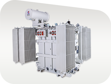
As load current flows through the primary and secondary copper or aluminum windings, I²R thermal losses generate heat. The surrounding transformer oil absorbs this heat energy, expands, decreases in density, and rises naturally toward the upper tank section. Hot liquid passes through external radiator panels or corrugated cooling fins, surrendering heat to ambient air before circulating back to the bottom tank entry. This continuous natural thermosiphon process (ONAN cooling) keeps core and winding hot-spot temperatures safely within IEEE/IEC thermal limits.
Structural Components of High-Reliability Distribution Transformers
To withstand extreme environmental conditions, transient lightning surges, and mechanical stresses induced by external short-circuit faults, Synergy Transformers engineers every oil-filled distribution unit using four critical subsystem modules:
- Magnetic Core Assembly: Fabricated exclusively from high-permeability, cold-rolled grain-oriented (CRGO) silicon steel laminations (M4, MOH, or laser-scribed grades). Lamination edges feature precision step-lap mitered joints (typically 45° step-lap geometry) to eliminate localized magnetic flux concentration, reduce magnetizing current, and drive no-load losses (P0) down to strict IS 1180 Level 2 / IEC Tier 2 efficiency mandates.
- Precision Winding Architecture: Winding configurations utilize either continuous round copper/aluminum wire or advanced high-density strip/foil conductors. High-voltage (HV) windings are insulated using thermally upgraded kraft paper, while low-voltage (LV) windings employ wide foil sheet geometry to distribute axial short-circuit forces evenly across the coil length.
- Dielectric Liquid & Tank Structure: High-grade mineral insulating oil conforming to IEC 60296 or IS 335 provides exceptional dielectric breakdown strength (>60 kV in treated state). Transformer tanks are manufactured in-house from heavy-gauge, low-carbon structural steel, featuring automated submerged-arc welding, shot-blasting surface pre-treatment, and multi-layer polyurethane or epoxy paint systems resistant to harsh marine and industrial atmospheres.
- Protection & Control Accessories: Outfitted with high-voltage porcelain or oil-filled polymeric bushings, off-circuit tap changers (OCTC) or on-load tap changers (OLTC), Buchholz relays for gas accumulation detection, magnetic oil level gauges (MOG), pressure relief devices (PRD), and dual-contact oil/winding temperature indicators (OTI/WTI).
Product Selection Guide 2. Recommended Oil Immersed Distribution Transformer Configurations
Matching the correct product design to specific site conditions, grid harmonics, and load dynamics is vital for maximizing operational reliability and preventing premature insulation thermal breakdown. Synergy Transformers provides a comprehensive range of field-tested, type-tested oil immersed distribution transformers tailored for global utilities, EPC contractors, and heavy industry.
Standard Utility Distribution Transformer
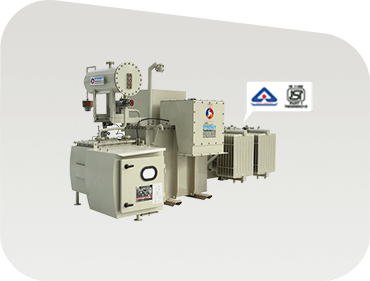
Designed for public power distribution feeders and rural electrification schemes. Built in hermetically sealed or conservator arrangements with option for IS 1180 Level 1 / Level 2 energy efficiency ratings.
16 kVA – 3150 kVA11kV / 22kV / 33kVBIS / IEC Approved
Features mitered CRGO cores, low temperature rise, and robust corrugated cooling fins for zero-maintenance utility operation.
Solar & Wind Inverter Duty Transformer
Engineered to step up variable low-voltage output from solar central inverters or wind turbine generators to high-voltage transmission lines under severe harmonic conditions.
K-Factor RatedMulti-Winding LVElectrostatic Shield
Includes grounded electrostatic shielding between primary and secondary coils to suppress high-frequency PWM inverter switching transients.
Compact Substation (CSS) Oil Unit
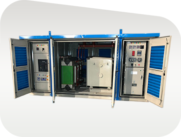
Integrated indoor/outdoor secondary distribution center housing medium-voltage SF6/VCB switchgear, oil-filled distribution transformer, and low-voltage distribution panel inside one weather-tight enclosure.
IP54 EnclosureIEC 62271-202Plug & Play
Ideal for space-constrained city centers, residential complexes, industrial parks, and commercial real estate developments.
Information Gain & Analytics 3. Technical Deep Dive: Total Cost of Ownership (TCO) & Loss Capitalization
When procuring an oil immersed distribution transformer, forward-thinking procurement teams recognize that the initial purchase price represents only 15% to 25% of the total cost incurred over the equipment's 30-year lifecycle. The remaining 75% to 85% is consumed by operational watt losses (no-load core losses $P_0$ and load copper losses $P_k$).
To quantify this long-term expenditure during technical bid evaluations, global utilities and industrial buyers apply standardized Loss Capitalization Formulas to calculate the true Total Cost of Ownership (TCO):
Lifecycle Total Cost of Ownership (TCO) Formula
The total evaluated cost of a transformer is expressed mathematically as:
TCO = C_purchase + (A × P_0) + (B × P_k)
Where:
- C_purchase: Initial capital purchase price ($ or local currency)
- P_0: Guaranteed no-load loss in kilowatts (kW) measured during open-circuit factory testing
- P_k: Guaranteed load loss in kilowatts (kW) measured at rated load and reference temperature (75°C)
- A: Capitalization value per kW of no-load loss ($/kW), reflecting 24/7 continuous core excitation
- B: Capitalization value per kW of load loss ($/kW), scaled according to expected plant load factor
Comparative Analysis: IS 1180 Loss Limits vs International Standards
The table below presents a comparative benchmark of loss levels for standard 33 kV class oil-immersed distribution transformers manufactured under Indian Standard IS 1180 (Level 1 vs Level 2 energy ratings) alongside corresponding IEC 60076 guidelines:
Technical Loss Benchmarks for 33 kV / 413V Oil Immersed Distribution Transformers | Rating (kVA) | IS 1180 Level 1 Max Losses (50% / 100% Load) | IS 1180 Level 2 Max Losses (50% / 100% Load) | Synergy High-Efficiency Guaranteed Max Losses | Impedance Voltage (%Z) |
| 100 kVA | 520 W / 1800 W | 435 W / 1500 W | 390 W / 1380 W | 4.50% |
| 250 kVA | 1050 W / 3150 W | 920 W / 2700 W | 810 W / 2450 W | 4.50% |
| 500 kVA | 1900 W / 5200 W | 1650 W / 4450 W | 1480 W / 4100 W | 5.00% |
| 1000 kVA | 3000 W / 9200 W | 2700 W / 8000 W | 2400 W / 7200 W | 5.00% |
| 2500 kVA | 6500 W / 21500 W | 5700 W / 18500 W | 5100 W / 16800 W | 6.25% |
Industry Foresight 4. Key Global Procurement & Technological Trends (2025–2035)
The global market for oil immersed distribution transformers is undergoing a massive structural shift driven by grid decarbonization, the integration of distributed energy resources (DERs), and stringent environmental safety mandates. Procurement officers and consulting engineers must account for three dominant industry trends when specifying transformers for new capital projects:
Trend A: Rapid Transition from Mineral Oil to Biodegradable Natural/Synthetic Esters
While uninhibited mineral oil has served as the default insulating fluid for over a century, natural ester fluids (derived from vegetable seeds like soybean or rapeseed) and synthetic esters are rapidly gaining market share. Ester fluids offer three vital operational benefits:
- K-Class High Fire Point (>300°C): Mineral oil flashes at approximately 140°C–160°C, classifying it as an O-class combustible fluid. Natural esters exceed 300°C fire points, drastically reducing substation fire hazards and enabling closer placement to industrial buildings without expensive blast walls.
- Environmental Protection: Natural esters biodegrade by >98% within 28 days (OECD 301 test), ensuring total compliance with environmental regulations in water catchment zones and coastal areas.
- Thermal Life Extension: Ester fluids actively absorb water molecules emitted by cellulose paper degradation, preserving paper tensile strength and extending overall insulation mechanical life by up to 30%.
Trend B: Adoption of Advanced Foil Winding for Short-Circuit Strength
Traditional distribution transformer coils used multi-layer round copper or aluminum wires. During external grid short circuits, unequal magnetic distribution causes severe axial forces that try to shear winding end-turns and collapse the coil structure.
Modern distribution transformer specifications increasingly mandate Aluminium or Copper Foil Winding Technology for low-voltage coils. By using a full-width continuous sheet of metallic foil insulated with epoxy resin paper, axial electromagnetic forces are virtually neutralized, conferring unmatched mechanical withstand capabilities during grid fault events.
Trend C: Integration of Online Condition Monitoring (Smart Distribution Transformers)
As part of the shift toward Industry 4.0 and Smart Grid automation, distribution transformers are evolving from passive assets into intelligent network nodes. Modern specifications require integrated sensor packages capable of transmitting real-time operational telemetry over Modbus, IEC 61850, or cellular IoT protocols:
- Online Moisture & Dissolved Gas Analysis (DGA): Micro-sensors measuring dissolved hydrogen ($H_2$) and moisture in oil (ppm) detect early thermal hot spots and partial discharge before catastrophic insulation failure occurs.
- Smart Breather Systems: Automated desiccant breathers with built-in heating elements automatically regenerate silica gel based on relative humidity, eliminating routine field maintenance visits.
- Digital Twin Thermal Modeling: Embedded firmware algorithms calculate real-time winding hot-spot temperature and loss of insulation life based on ambient temperature and dynamic load currents.
Proven Expertise 5. Why Leading Global Procurement Teams Choose Synergy Transformers
Founded in 2004 in Rajkot, Gujarat, India, Synergy Transformers Pvt. Ltd. has grown into an internationally recognized manufacturer of high-reliability distribution, power, dry-type, furnace, and renewable inverter-duty transformers. Operating from a world-class 103,500+ sq. ft. built-up manufacturing facility, Synergy maintains absolute control over every stage of transformer fabrication.
In-House Manufacturing Integration
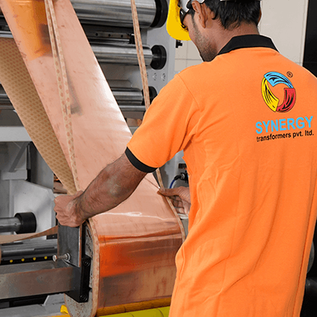
Unlike assemblers who outsource critical components, Synergy executes core cutting, coil winding, tank fabrication, surface treatment, oil processing, and high-voltage testing under one ISO-certified quality management framework.
- Automated CNC step-lap CRGO core cutting lines
- Precision foil winding machinery for low voltage coils
- In-house heavy steel tank fabrication & shot blasting
- Seven-tank surface treatment & powder coating bay
- High-vacuum oil filtration & degasification plants
- Fully equipped routine & type testing laboratory
Quality Assurance & Witness Testing Standard
Every single oil immersed distribution transformer leaving the Synergy facility undergoes rigorous routine testing strictly compliant with IEC 60076, IS 2026, and IS 1180 standards. Global buyers and third-party inspection agencies (TUV, SGS, Bureau Veritas, Intertek, DNV) are routinely welcomed to witness factory acceptance testing (FAT) inside our Rajkot testing facility.
100% Quality Routine Test Coverage
Routine test reports issued with every transformer include: Measurement of Winding Resistance, Voltage Ratio and Vector Group Check, Impedance Voltage & Short-Circuit Losses, No-Load Loss & Current Measurement, Separate-Source Voltage Withstand Test, Induced Overvoltage Withstand Test (DVDF), and Oil Dielectric Breakdown Strength (BDV) verification.